Product Overview & Buyer Intent Summary
Jiangsu Liangyi Co., Limited has more than 25 years of open die forging experience serving the global power generation industry. Our forged steel gas and steam turbine rotor shafts are widely used in medium-capacity turbine units and other critical rotating equipment where high mechanical integrity, low internal defect risk and reliable heat treatment performance are required.
This page is designed to answer the questions that engineers, procurement teams and EPC contractors mainly ask before sending drawings or an RFQ: what types of rotor shafts are available, which material grades can be supplied, what standards are covered, how the forgings are manufactured, how inspection is controlled, what sizes can be produced, and how global market requirements are handled. It is also written to support buyers searching for a qualified steam turbine rotor shaft manufacturer, a custom turbine generator rotor shaft forging source or a dependable supplier for replacement and retrofit shaft projects.
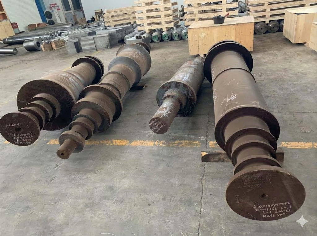
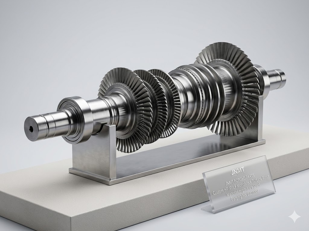
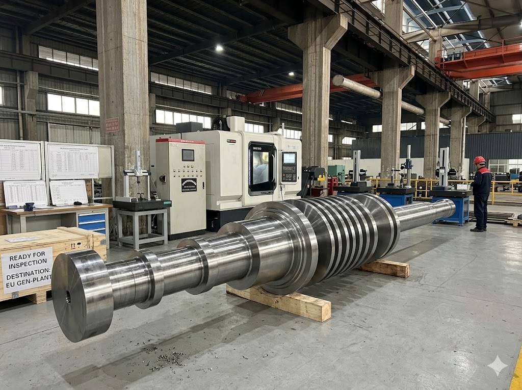
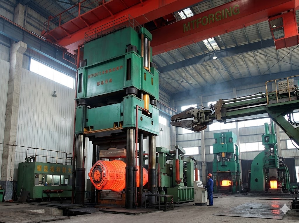
From left to right: a finished rotor shaft (single-piece weight up to 30 tons), a custom shaft configured with separate HP/IP and LP sections, and a shaft at the machining-preparation stage.
Buyer Choice Guide & Evaluation Checklist
Before placing an order for a custom rotor-shaft forging, these are the points worth confirming with any supplier. They decide manufacturability, inspection scope and realistic delivery.
1. Confirm the shaft type
Check whether the use requires an HP/IP rotor shaft body, LP turbine generator hollow shaft or a mono block rotor design.The geometry of the shaft affects the forging route, heat treatment and inspection strategy.
2. Match the material with the use conditions
Material choice should reflect the operating temperature, creep requirements, impact requirement, corrosion environment, rotational speed and engineering specifications.
3. Verify process depth
Ask the supplier whether they have internal control over melting, optional ESR/VAR, forging, heat treatment, machining and non-destructive testing, or whether critical stages are outsourced.
4. Review inspection scope
For the rotor shaft, inspection should go beyond chemistry and hardness, including controls related to UT, MT, PT, metallography, dimensional verification and residual stress.
5. Confirm the standards and documents
The project team should verify the required ASTM, DIN, EN, GOST, JIS or ASME routes, as well as whether 3.1/3.2 certification or third-party witness inspection is needed..
6. Evaluate the authenticity of the delivery date
Large custom forgings require an actual production window. A reliable supplier should explain how the material route, heat treatment and inspection steps affect the final delivery.
Technical Specifications
Key decision data at a glance:
| Item | Details |
|---|---|
| Product name | Forged steel gas & steam turbine rotor shafts |
| Common shaft types | HP/IP steam turbine rotor shaft bodies, LP turbine generator intermediate hollow shafts, custom mono block rotor shafts |
| Applicable turbine range | 35MW, 50MW, 60MW and 70MW steam and gas turbine applications |
| Maximum single-piece weight | 30 tons |
| Maximum ingot weight | 50 tons |
| Maximum diameter | 1800 mm |
| Maximum length | 15 meters |
| Main standards | ASTM, DIN, EN, GOST, JIS, ASME |
| Optional remelting | ESR and VAR |
| Certification documents | ISO 9001:2015 and EN 10204 3.1 / 3.2 MTC |
| Normal Lead time | 60-90 days; urgent projects may be shorten to about 45 days |
Uses, Challenge & Why Do Buyers Choose This Product
The rotor shafts of steam turbines and gas turbines operate under the combined stress of high temperature, high pressure, high speed and long-term continuous operation. As these axes are located at the center of the rotating train, even minor internal defects or process instability can lead to size drift, crack initiation, forced shutdowns or catastrophic failures.
Typical challenges include high-temperature creep, thermal fatigue, internal porosity, residual stress, slow delivery caused by a fragmented supply chain, and uncertainty about compliance with regional standards. None of these are marketing-level issues; They directly affect operational safety, life cycle costs and project approval speed.
For buyers comparing a gas turbine rotor shaft forging with a traditional steam-turbine use, the technical emphasis may differ. Gas-turbine-related projects often place stronger focus on thermal-cycle response, alloy cleanliness, fatigue resistance and heat-treatment repeatability, while forged steam turbine rotor shafts for utility use often require broader attention to creep strength, size stability, rotor straightness, long-shaft machining accuracy and documents for third-party approval.
Targeted solution: Jiangsu Liangyi has solved these problems through a full-process manufacturing route that includes controlled steelmaking, optional ESR/VAR remelting, open die forging with appropriate forging ratios, precise heat treatment, multi-round processing, and 100% non-destructive testing before leaving the factory.
From the perspective of procurement, customers do not merely need a forging supplier; They need a partner who can reduce approval delays, clearly explain inspection logic, confirm manufacturability before production and lower the risk of costly rework. This is particularly important for custom forged rotor shafts used in power plant renovations, as on-site dimensions, existing coupling interfaces and downtime schedules will directly affect project decisions.
High-temperature reliability
Material cleanliness, heat treatment control and appropriate alloy choice have enhanced creep and fatigue resistance.
Lower defect risk
Repeated ultrasonic testing and metallurgical verification help identify internal defects before final delivery.
Faster project response
Integrated in-house capability reduces handoff risk and shortens lead time for custom forgings.
Main Turbine Rotor Shaft Types Supplied
The product scope covers new-build and replacement requirements for buyers sourcing a forged rotor shaft for steam turbine generator, an intermediate shaft for utility equipment, or a special geometry forging for retrofit and aftermarket service.
HP/IP Steam Turbine Rotor Shaft Bodies
These forgings are used in high-pressure and medium-pressure sections where the requirements for temperature and stress levels are particularly high. Material choices and tempering response are crucial for long-term stability in use..
LP Turbine Generator Intermediate Hollow Shafts
The internal channel conditions, robustness and residual stress of the low-pressure rotor shaft and the intermediate hollow shaft need to be carefully controlled. This is particularly important for large hollow forgings and applications that require low vibration and stable alignment.
Custom Mono block Turbine Rotor Shafts
Mono block designs are used where customers want fewer assembled interfaces and stronger overall integrity.They are often defined based on client drawings, stress calculations, and performance standards for the whole project.
Material Grades, Metallurgy & Standards Accordance
We manufacture forged gas and steam turbine rotor shafts using mature alloy steel grades for turbine services. The choice of materials depends on the working temperature, the required strength, creep resistance, impact requirements, the geometry of the shaft and the project specifications.
Melting & Refining Route
Steel can be smelted in an electric arc furnace, refined and vacuum treated. ESR or VAR can be chosen according to project requirements. The aim is to enhance cleanliness, reduce non-metallic inclusions, improve uniformity, and increase reliability under cyclic and high-temperature loads.
Ingots are always sized above the finished forging weight to allow for forging reduction and end-cropping — up to 50 tons for our largest rotor shafts. For large ingots, vacuum degassing and protective teeming are used to reduce porosity and shrinkage. This metallurgical control is crucial for rotor-shaft forgings, since internal soundness directly affects fatigue resistance and service life.
Standards & Documents
- ASTM A470 / A472 and related project specifications
- DIN and EN grade equivalencies where required
- GOST and JIS routes for regional projects
- ASME-oriented accordance with customer or EPC requirements
- EN 10204 3.1 / 3.2 mill test certification and third-party inspection support
Which Rotor Steel for Which Turbine Section?
Rotor-shaft steel is chosen first by metal temperature and the duty of the turbine section. The grades below cover most steam- and gas-turbine rotor work — click a grade for full chemistry, properties and certification. Final selection always follows the customer drawing and project specification.
| Grade | Typical section | Approx. metal-temperature ceiling | Chosen when… |
|---|---|---|---|
| 26NiCrMoV14-5 (1.6957) | LP rotors, generator rotors, large intermediate shafts | ≈ 350 °C | Toughness and deep hardenability matter more than creep — large, cooler-running sections where through-thickness properties are critical. |
| 28CrMoNiV4-9 (1.6985) | HP / IP rotors | ≈ 540 °C | A balance of creep strength and toughness is needed for medium-to-high-temperature HP/IP service. |
| 30CrMoNiV5-11 (1.6946) | HP / IP rotors | ≈ 565 °C | Higher creep strength is required at the top of the CrMoV range. |
| X22CrMoV12-1 (1.4923) | HP rotors, high-temperature stages, blading | ≈ 565–600 °C | Oxidation and creep resistance above the CrMoV ceiling call for a 12% Cr martensitic steel. |
| ASTM A470 / A472 (Cr-Mo-V) | HP / IP rotors (US / ASME projects) | ≈ 540 °C | The project is specified to ASTM / ASME rather than EN / DIN. |
Temperatures are indicative class limits, not guarantees — the actual allowable temperature depends on stress, design life and the heat-treatment condition agreed for your order.
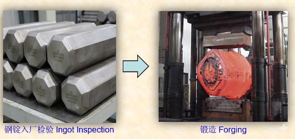
Full-Scale Manufacturing Process
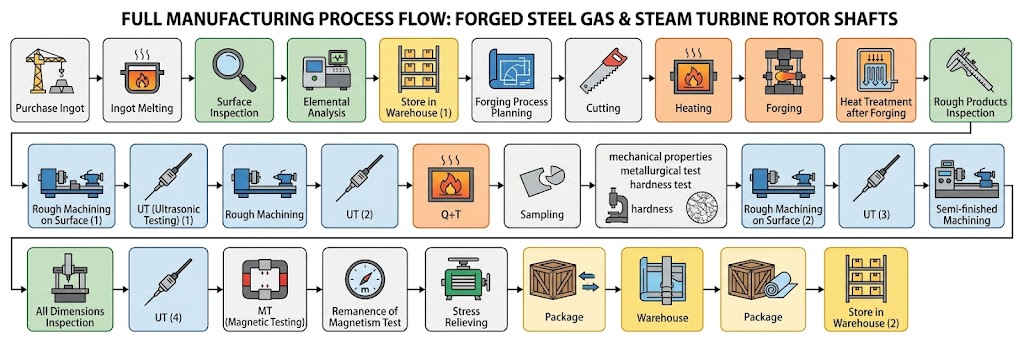
Each forging follows a traceable route from raw material to finished product. The aim is not only to meet chemistry and mechanical property requirements, but also to maintain process consistency, internal soundness and size stability across the full manufacturing chain.
- Raw material qualification: purchase or melt qualified alloy steel, then perform surface inspection and chemistry verification.
- Process design: define forging route and allowances according to shaft type, material grade and service condition.
- Controlled heating: use gradient heating to reduce thermal shock and crack risk.
- Open die forging: By adopting multi-directional deformation, the forging ratio is no less than 4:1, the grains are refined and the interior is dense.
- Normalization: remove part of the forging stress and improve structure uniformity.
- Rough machining + UT: identify internal defects as early as possible in the process.
- Secondary rough machining + UT: expand defect coverage before final heat treatment decisions.
- Quenching and tempering: get target strength, toughness and structural response.
- Sampling and laboratory testing: Check the mechanical properties, hardness, and metallographic conditions by taking samples and testing them in a lab.
- Semi-finishing: get the exact shapes ready for final inspection.
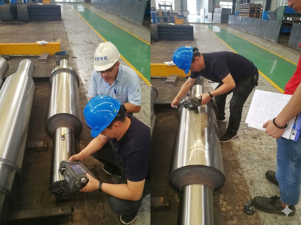
- Final NDT: UT, MT, PT, and other checks before the product leaves the factory.
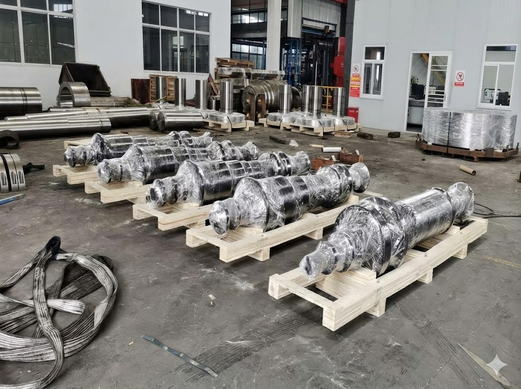
- Stress relieving, packing and dispatch: protect long-term size stability and shipping quality.

Production Equipment & In-House Capacity
Our equipment base supports heavy open die forging, heat treatment of long shafts, rough-to-finish machining and laboratory plus non-destructive inspection. This in-house depth reduces dependency on external subcontractors and improves schedule control.
Forging Equipment
- 2,000t, 4,000t and 6,300t hydraulic forging presses
- 1–5t electro-hydraulic forging hammers and forging manipulators
- Seamless ring rolling up to 5 m diameter
- 30t EAF + LF + VOD melting, with optional ESR / VAR for high-cleanliness grades
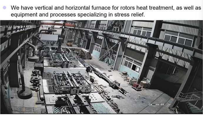
Heat Treatment Equipment
- Computer-controlled pit furnace for long shaft heat treatment
- Large table resistor furnace with precise temperature control
- Box furnaces for samples and process support
- Multiple natural gas furnaces for large workpieces
Machining & Inspection Equipment
- Heavy CNC lathes for long-shaft machining
- CNC vertical lathe and floor-type boring and milling machines
- 5-axis machining and supporting precision equipment
- Metallographic, tensile, impact, hardness and full NDT testing equipment
What We Can — and Cannot — Forge
Being clear about limits saves everyone time. This is the honest envelope for our rotor-shaft work:
Within our capability: open-die forged monoblock and stepped rotor shafts in the grades above, melted in-house with optional ESR / VAR and supplied with EN 10204 3.1 / 3.2 certification. Finished single-piece weight up to 30 tons, from ingots up to 50 tons, with diameter up to 1,800 mm and length up to 15 m. For shafts that run hot, we also perform in-house heat stability (thermal runout) testing to SEP 1950.
Outside our capability — where we will point you elsewhere:
- Rotor shafts requiring an ingot above 50 tons or a finished weight above 30 tons — beyond our press and ingot capacity, these belong to dedicated heavy-forging houses, and we will say so up front.
- Cast rotor shafts — we forge, we do not cast.
- Complete rotor assembly, final blading and high-speed dynamic balancing of the finished rotor train — we supply the forged and machined shaft; final assembly and balancing stay with the turbine builder.
If a project sits outside this envelope, tell us anyway — we would rather direct you to the right source than over-promise.
Vertical Heat Treatment — Engineered for Straight, Stable Rotor Shafts
We quench and temper rotor shafts vertically, suspended in a deep computer-controlled pit (well-type) furnace, instead of lying them down horizontally. For a long turbine shaft this one choice drives straightness, microstructure uniformity and — ultimately — whether the shaft passes its heat stability test.
Why vertical, not horizontal
- No gravity sag. At austenitizing and tempering temperatures a long shaft left horizontal sags under its own weight and locks in a permanent bow. Hung vertically, the shaft carries its own weight in pure axial tension and stays straight — protecting straightness and low runout.
- Symmetric, uniform heating. Suspended in the pit furnace the shaft sees even temperature around its circumference and along its length, so austenitizing and transformation are uniform end-to-end and surface-to-core — uniform grain structure and consistent mechanical properties.
- Even quench. Quenched vertically, the shaft cools symmetrically all around, avoiding the top-versus-bottom temperature split a horizontal shaft sees in the bath. Even cooling means less quench distortion and more symmetric residual stress.
The payoff: it stays true at temperature
Symmetric residual stress and uniform thermal expansion are exactly the conditions a rotor needs to remain straight when it is hot. This is the upstream reason our shafts behave well in the SEP 1950 heat stability test: the vertical-furnace route minimises the asymmetric residual stress and non-uniform expansion that cause hot runout. Heating and cooling rates are program-controlled, and residual stress is held within agreed limits before the shaft moves to final machining.
Quality Control, NDT & Thermal Stability
The key points of rotor shaft quality control are internal robustness, residual stress, microstructure, dimensional stability and verification of mechanical properties. This is particularly important for forgings that will operate continuously at high temperatures and high speeds.
Residual Stress Control
Residual stresses in forged turbine rotor blanks are strictly controlled to not exceed 49 MPa (5 kgf/mm²). Blanks with body diameter over 400 mm are tested, and slow furnace cooling after final tempering is used to reduce deformation risk during service.
Inner Channel Examination for Hollow Shafts
For hollow LP turbine and generator rotor shafts, the inner bore is examined by periscope (bore-scope) for cracks, spalling, porosity, shrinkage cavities and excessive non-metallic inclusions, and held to agreed limits to keep the shaft fit for service and further machining.
- No non-metallic impurities longer than 3 mm in the defined inspection area
- Strict total-count limits for isolated impurities and cluster distribution
- Controlled boring or spot grinding allowances where needed within agreed tolerances
Heat Stability (Thermal Runout) Test to SEP 1950
For rotor shafts that must stay true at operating temperature, we carry out the heat stability test (Warmrundlauf) to SEP 1950 on our in-house rig. The finished, concentrically machined shaft is slowly rotated and heated uniformly to a test temperature below its tempering temperature, held, then cooled, while the radial runout is recorded electronically along the body. This confirms the shaft is thermally and radially stable — free of distortion from residual-stress release or non-uniform thermal expansion — before it reaches your turbine. If runout exceeds the agreed limit, we re-stress-relieve or re-temper and repeat the test. The full record, including the runout–temperature–time curve and the hot/cold polar diagram, is supplied with the shaft. This test is offered with the customer and is not something every forge can run in-house.
Documented Case — 28CrMoNiV4-9 Rotor, SEP 1950 (Pass)
A real example from our records: a forged 28CrMoNiV4-9 (1.6985) turbine rotor, heat-stability tested to SEP 1950-1997 in January 2023. The shaft was rotated and heated to a 620 °C test temperature (set relative to the shaft's tempering temperature per SEP 1950, not its service temperature), held, then slow-cooled over a multi-day cycle. Radial runout was recorded hourly at five axial measuring zones and eight angular positions (every 45°) through evaluation points I–IV (initial cold, at temperature, hot, final cold).
Result: pass. The resulting runout change between the hot and final-cold states was essentially zero — within about 0.02 mm at every measuring zone — well inside the SEP 1950 acceptance limit, confirming the rotor stays true at temperature. The complete record (hourly runout tables, per-zone polar diagrams and the temperature/runout-vs-time curve) is issued with the shaft.
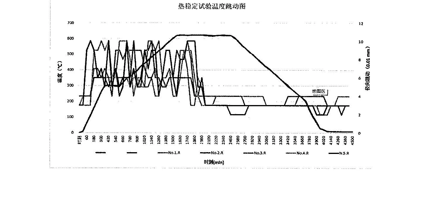
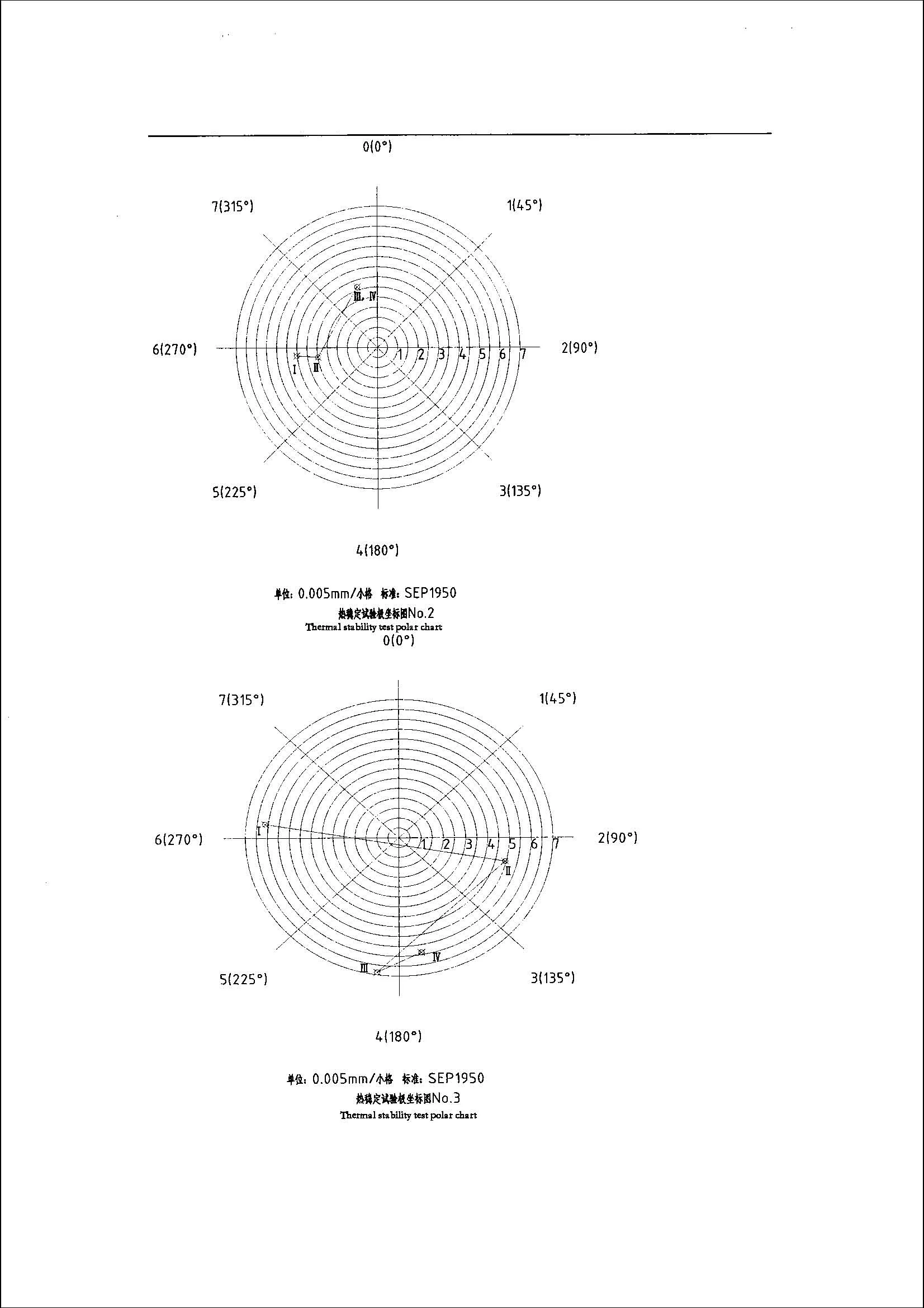
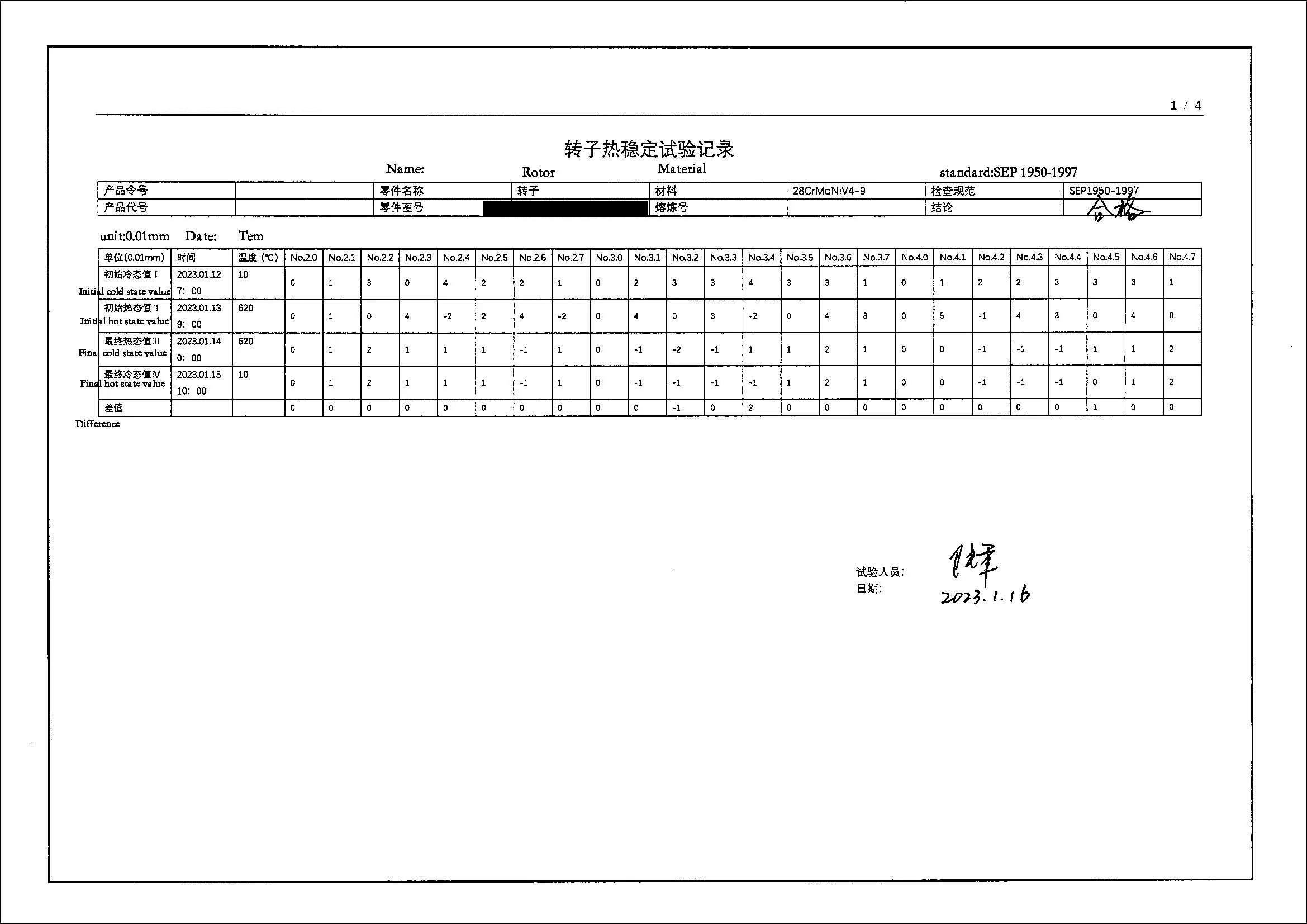
Test documentation is shown with customer-identifying details (drawing and order numbers) redacted for confidentiality.
Mechanical & NDT Package
- Room-temperature and high-temperature tensile testing
- Charpy V-notch impact testing
- Brinell and Rockwell hardness testing
- Macro-etching and metallographic inspection
- 100% ultrasonic testing
- Magnetic particle inspection
- Liquid penetrant inspection
- Size, visual, metrological and high-temperature measurement verification
Rotor-Shaft Forging Defects — and How We Control Them
Large rotor-shaft forgings fail review for a predictable set of metallurgical reasons. These are the ones we design the process around, with the specific controls applied before a shaft is released:
| Risk | Why it happens | How we control it |
|---|---|---|
| Centre segregation & central unsoundness | Chemical segregation and shrinkage porosity concentrate at the core of heavy ingots. | Vacuum-degassed melting (ESR / VAR where specified) for cleanliness; a high forging ratio with proper upsetting and drawing to consolidate the core; core soundness verified by ultrasonic testing. |
| Hydrogen flakes / white spots | Dissolved hydrogen in thick sections forms internal cracks during cooling. | Vacuum degassing to drive hydrogen down to a low ppm level, then controlled slow cooling and a dehydrogenation (anti-flake) hold; confirmed by UT. |
| Residual stress & distortion | Heavy quench-and-temper builds in residual stress that later causes runout or dimensional drift. | Rough machining before final heat treatment, controlled tempering, slow furnace cooling and stress relief; residual stress held within agreed limits and straightness checked. |
| Inclusion clusters → UT indications | Non-metallic inclusion clusters scatter ultrasound and can exceed acceptance limits. | Clean steelmaking (LF + VOD, optional ESR), low-sulphur practice, and flat-bottom-hole UT acceptance to the agreed standard; bore-scope inspection for hollow shafts. |
| Surface decarburization | Prolonged high-temperature heating depletes surface carbon, lowering surface hardness and fatigue strength. | Controlled heating time and atmosphere plus sufficient machining allowance to remove the decarburized layer, with surface hardness verified after machining. |
| Temper embrittlement | CrMoV / NiCrMoV rotor steels lose toughness if held in or slow-cooled through the embrittlement range, especially with high tramp elements. | Low-tramp melt practice (controlled P, Sn, As, Sb), avoiding slow cooling through the embrittlement range after tempering, with toughness / FATT verified on test samples. |
Each control above is reflected in the inspection records and certificate package supplied with the shaft.
Global Market Adaptation & Main Project Direction
Rotor-shaft orders are judged less on size and weight than on whether the forging route, metallurgy, inspection scope and certificate package match the destination market's standards. The recurring project risks are not only mechanical-property shortfalls but documentation mismatches, size drift after heat treatment and thin inspection evidence at final approval — so we agree standards and inspection depth before production. The standards we most often work to, by region:
| Region | Standards we commonly work to |
|---|---|
| North America | ASTM A470 / A472, ASME BPVC, utility project specifications |
| Europe | DIN EN material routes, PED-related pathways, customer QA systems |
| Middle East | Saudi Aramco (SAES), ADNOC, EPC and ASTM project frameworks |
| Asia-Pacific | GB, JIS, AS/NZS and OEM / utility technical specifications |
| Southeast Asia | ISO, IEC and local utility / import approval requirements |
| Latin America | ASTM, ISO and EPC / aftermarket maintenance specifications |
For a regional project, the fastest route to an accurate quote is to send the drawing, target standard, working temperature, inspection scope, certificate requirements and required delivery window together.
RFQ Preparation & Documentation Checklist
What to prepare so we can return an accurate quotation and technical review quickly:
What to send in your RFQ
Include drawing number, shaft type, material grade, applicable standard, quantity, target delivery date, heat treatment requirement, machining allowance, inspection scope and required certificates.
Main documents buyers request
Common requests include MTC, heat-treatment records, NDT reports, size inspection reports, mechanical test reports and third-party witness documents where required.
What we confirm before production
Manufacturability against your drawing, the ingot and forging route, the heat-treatment plan, inspection scope and certificate package — agreed in writing before the order is released, to avoid rework and approval delays.
For large forgings, a complete RFQ means a faster, more accurate quotation and fewer rounds of clarification.
Frequently Asked Questions
What is the maximum weight and size of forged turbine rotor shafts you can produce?
We can produce forged steel gas and steam turbine rotor shafts with maximum single-piece weight up to 30 tons, maximum diameter up to 1800 mm and maximum length up to 15 meters.
What international standards do your turbine rotor shafts meet?
Products can be supplied according to ASTM A470/A472, DIN EN, GOST, JIS, ASME and project-specific requirements, with EN 10204 3.1 / 3.2 certification available.
Can you perform a heat stability (thermal runout) test on the rotor shaft?
Yes. We carry out the heat stability test (Warmrundlauf) to SEP 1950 on our in-house rig and supply the full test record — the runout–temperature–time curve and the hot/cold polar diagram — verifying the shaft stays radially stable at operating temperature. This is agreed with the customer at order stage.
What is the normal delivery cycle for custom turbine rotor shafts?
Normal lead time is 60-90 days depending on sizes, material grade and quantity. Urgent projects may be shortened to around 45 days when production scheduling allows.
Can you provide ESR or VAR remelting?
Yes. ESR and VAR can be supplied when higher material cleanliness and improved high-temperature fatigue performance are required.
Do you support production according to our drawings?
Yes. Most projects are custom manufactured according to client drawings and technical manuals, and technical discussion can start from an inquiry, drawing package or required standard list.
How do you control internal soundness for large forged steam turbine rotor shafts?
Internal soundness is controlled by melting and refining discipline, optional ESR / VAR, forging ratio control, staged rough machining, repeated ultrasonic testing, metallographic verification and final NDT review before release. This helps reduce the risk of hidden discontinuities that could affect service life.
What documents can be provided for export projects?
Depending on the project scope, we can support MTC, heat treatment records, ultrasonic and surface NDT reports, size inspection reports, mechanical test results, traceability records and EN 10204 3.1/3.2 certification.
Inquiry & Contact Information
Jiangsu Liangyi Co., Limited is a manufacturer of open die forgings and seamless rolled rings with an annual production capacity of 120,000 tons in China. We support custom forged parts from 30 kg to 30,000 kg and provide technical review for forged steel gas and steam turbine rotor shafts according to client drawings and project requirements. For buyers comparing suppliers, this page is intended to function as both a technical reference and a direct contact point for a qualified steam turbine rotor shaft manufacturer.
To receive a quotation faster, include your drawing, material grade, standard, quantity, delivery schedule, heat treatment requirement, NDT level and certification requirement in your inquiry.