About AISI 9310 Carburizing Alloy Steel Forgings
Established in 1997, Jiangsu Liangyi Co.,Limited has spent over 25 years building deep process expertise in open die forging and seamless ring rolling of high-alloy steels, with AISI 9310 (also known as SAE 9310, UNS G93100, and Alloy 9310) being one of our core production materials. Our 80,000㎡ Jiangyin facility runs a fully integrated production flow — from incoming billet chemistry verification, multi-step open die forging with controlled reduction ratios, CNC-programmable heat treatment, and precision machining, to final non-destructive examination — with every process parameter recorded and traceable. Material composition and mechanical testing are performed in our in-house laboratory to the requirements of ASTM A534, AMS 6265, and other applicable standards.
What Makes AISI 9310 Unique Among Carburizing Steels
Among all carburizing alloy steels, AISI 9310 occupies a distinct position due to its exceptionally high nickel content (3.00–3.50%), which is approximately 3–5 times the nickel level found in more common grades such as AISI 8620 or 4320. This high nickel level is the defining feature of 9310, and it directly produces three engineering advantages that are difficult to replicate with lower-alloy alternatives:
- Superior through-hardenability in large cross-sections: The Ni-Cr-Mo ternary alloying combination dramatically suppresses the pearlitic and bainitic transformation, allowing the steel to fully harden even in thick-section forgings — an essential property for large planetary gear rings or heavy-duty pinion shafts where section sizes routinely exceed 200mm.
- Deep, uniform case depth after carburizing: High nickel slows carbon diffusion rates just enough to allow carburizing carbon gradients to distribute more evenly from surface to core transition zone, resulting in a smoother hardness gradient and reduced risk of case-core interface cracking under cyclic contact loading — the primary failure mode in heavy gear applications.
- Preserved core toughness at hardened surface conditions: After carburize-and-quench, the AISI 9310 core retains Charpy impact values typically above 68 J (50 ft-lbf) at room temperature — a characteristic that common carburizing grades often cannot sustain at equivalent strength levels. This combination of hard case and tough core defines what gear engineers refer to as "case hardened integrity."
Why Forging — Not Bar Stock or Casting — Matters for 9310
The performance advantages of AISI 9310 chemistry are only fully realized when the material is processed via forging rather than simply machined from rolled bar or cast. Open die forging closes the inherent porosity and segregation present in any as-cast ingot structure, breaks up dendritic carbide networks, and — critically — aligns the grain flow to follow the geometry of the final component. In a gear shaft, for example, a correctly forged billet produces grain flow that wraps around the fillet radii and tooth roots, placing the strongest grain boundaries perpendicular to the highest tensile stresses during operation. This is why AISI 9310 forged gear components consistently demonstrate bending fatigue and contact fatigue lives 30–50% longer than equivalent machined bar components in controlled test comparisons. At Jiangsu Liangyi, we maintain a minimum forging ratio of 3:1 for all 9310 work — and for critical cross-section components, we target 4:1 or higher — specifically to guarantee the full structural benefit of the forging process is delivered to the finished part.
Custom AISI 9310 Forged Shapes & Manufacturing Capabilities
Our production capability covers the full spectrum of forged shapes that industrial clients require for AISI 9310 applications. Every shape below is produced from a single-heat billet — never welded or joined assemblies — maintaining the continuous grain flow integrity that is the entire engineering rationale for choosing forgings over fabrications. All shapes can be supplied as rough forged, rough machined, or finish machined to your drawing tolerances.
📏 Forged Bars & Stepped Shafts
Round, square, flat, and hexagonal bars; single-step and multi-step shafts with up to 8 diameter transitions per piece. Weight range: 30 kg to 30,000 kg. Length up to 12 meters for single-heat bar forgings. Ideal as machining blanks for custom shaft, spindle, and pin applications where the customer's own CNC shop handles final profiling.
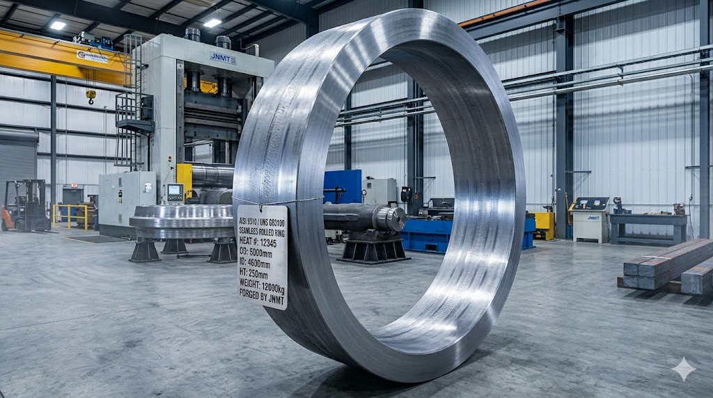
⚙️ Seamless Rolled Rings
Produced on our radial-axial ring rolling mill: OD range 300mm–5,000mm, height up to 1,200mm, wall thickness ratio (OD/ID) from 1.15:1 to 3:1. Profiles include flat rings, flanged rings, profiled rings (L-section, T-section), and near-net-shape gear rims with pre-formed tooth root geometry. Grain flow is circumferential throughout — the only way to resist hoop stresses in rotating machinery.
🔩 Gear Blanks & Pinion Shafts
The primary application of AISI 9310 forgings. Gear blanks forged to within 5–8mm of the finish OD, with datum bore and face machined to H7 tolerance as standard. Pinion shafts available with integral flange, spline, or journal features forged-in. Case depth after carburizing: 0.8–2.5mm, specified and controlled to your drawing requirement.
🏭 Hollow Forgings & Thick-Wall Cylinders
Mandrel-forged hollow bars, sleeves, and cylinder bodies with controlled wall uniformity: wall eccentricity ≤ 5% of nominal wall thickness as standard. Bore as-forged or rough bored. For pressure-retaining applications, forgings can be supplied with full UT scan coverage to confirm internal soundness before machining — saving significant downstream cost.
📦 Discs, Hubs & Flanged Forgings
Flat discs, hub blanks, flange forgings, and plate forgings with forged-in boss features. Aspect ratio from thin disc (H/D = 0.1) to thick disc (H/D = 1.0). Particularly suited to planet carrier bodies, coupling hubs, bearing end caps, and large valve gate blanks where the low-carbon 9310 composition provides excellent machinability in the annealed condition before final heat treatment.
🔧 Custom Near-Net-Shape Forgings
For customers seeking to minimize machining time and material waste, we work from your 3D model to develop a custom forging die or tooling layout. Near-net-shape open die forgings typically achieve 60–75% buy-to-fly ratio improvement vs. machining from solid bar on complex geometries. DFM (Design for Manufacturability) review provided at no charge with initial inquiry.
Have a drawing or specification? Send it to us — we'll review your geometry and return a DFM assessment and competitive quote within 24 hours.
Send Drawing for Free QuoteChemical Composition of AISI 9310 Steel — Element by Element
We source AISI 9310 billets exclusively from steel mills that supply mill test certificates with full heat analysis. Each incoming lot is independently re-tested in our own spectrometer laboratory before release to the production floor. The composition ranges below are per ASTM A534. The third column explains the metallurgical function of each element — understanding this is the key to specifying and accepting 9310 with confidence.
| Element | ASTM A534 Range | Engineering Role in AISI 9310 |
|---|---|---|
| Carbon (C) | 0.07% – 0.13% | Intentionally low to keep the core ductile and machinable. Surface carbon is later added by carburizing, allowing the surface and core properties to be engineered independently — the fundamental principle of the grade. |
| Nickel (Ni) | 3.00% – 3.50% | The defining element of 9310. High nickel (3–4×) increases hardenability, lowers the ductile-to-brittle transition temperature for superior low-temperature toughness, and stabilizes martensite in thick sections. No other common carburizing grade approaches this Ni level. |
| Chromium (Cr) | 1.00% – 1.40% | Works with Ni and Mo to create the ternary hardenability effect. Cr also forms stable carbides that resist softening during carburizing and improves surface wear resistance of the carburized case. Boosts oxidation resistance during heat treatment. |
| Molybdenum (Mo) | 0.08% – 0.15% | Suppresses temper embrittlement — a critical role when components must be tempered in the 150–200°C range after quenching. Mo also refines austenite grain size during carburizing, improving fatigue crack initiation resistance at the case-core boundary. |
| Manganese (Mn) | 0.40% – 0.70% | Secondary hardenability contribution and deoxidizer. Kept moderate to avoid excessive banding segregation in heavy forgings, which would create property directionality in the final machined component. |
| Silicon (Si) | 0.15% – 0.35% | Deoxidizer during steelmaking. Silicon content at this level also slightly strengthens the ferrite matrix in the core without degrading toughness. Higher Si would impair carburizing response and is intentionally avoided. |
| Phosphorus (P) | ≤ 0.015% max | Strictly controlled impurity. P segregates to grain boundaries during solidification and dramatically reduces impact toughness especially at low temperatures. The 0.015% limit is stricter than the norm for steel grades and is due to the toughness requirements of 9310 applications. |
| Sulfur (S) | ≤ 0.015% max | Strictly controlled impurity. S forms manganese sulfide (MnS) inclusions that act as fatigue crack initiation sites. The 0.015% cap aligns with the fatigue-critical nature of most 9310 gear and shaft applications. |
| Boron (B) | ≤ 0.001% (10 ppm) | Residual element control. Even trace boron (>10 ppm) can unpredictably increase hardenability and cause cracking during quench. The 10 ppm limit guarantees the Ni-Cr-Mo hardenability mechanism operates as designed, without unintended boron contribution. |
| Copper (Cu) | ≤ 0.035% max | Residual from scrap-based steelmaking. At levels above ~0.2%, Cu can cause hot shortness (surface cracking) during hot forging. The 0.035% limit provides a generous safety margin for the elevated forging temperatures used in 9310 processing. |
One practical note for procurement engineers: when requesting mill test certificates, verify that both the ladle analysis and the product analysis (check analysis from the actual forging stock) are reported. Ladle analysis reflects the furnace melt chemistry; product analysis — conducted on the rolled or forged product — may show slightly different values due to segregation and processing. At Jiangsu Liangyi, we report both in our material documentation package as standard practice.
AISI 9310 International Equivalent Grades — Practical Cross-Reference
Many engineering projects originate with a drawing specifying a national standard other than AISI/SAE. The table below lists the closest international equivalents to AISI 9310 (UNS G93100) and includes the critical caveat column that most cross-reference tables omit: the key compositional differences that can affect interchangeability in demanding applications. Our engineering team reviews substitution requests on a case-by-case basis and can supply a written material equivalency letter for your procurement record.
| Standard / Country | Designation | Key Difference vs. AISI 9310 |
|---|---|---|
| USA — SAE / UNS | SAE 9310, UNS G93100, AMS 6265, AMS 6267, ASTM A534 | Direct standard — no substitution involved. AMS 6265 covers bar stock; AMS 6267 covers billet for forging stock. ASTM A534 covers bearing quality bar and rod. |
| Germany — DIN / EN | 1.6587 / 18CrNiMo7-6 | Ni content in 18CrNiMo7-6 is 1.40–1.70% — significantly lower than 9310's 3.00–3.50% Ni. Suitable for many gearbox applications, but lower Ni reduces toughness in thick sections and at low temperatures. Specify AISI 9310 explicitly for thick sections >150mm or sub-zero service. |
| Europe — EN | EN 10084: 15NiCrMo16-5 (1.6723) | Closer Ni equivalent (~3.6–4.1% Ni) making this the most directly comparable European grade. Slightly higher Ni floor; generally interchangeable in most gear applications with written material review. |
| United Kingdom — BS | 826M31 / EN 39B | Older British designation system. 826M31 aligns reasonably well but has looser composition tolerances than ASTM A534. EN 39B is closer to 9310 Ni level. Both are now largely superseded by EN 10084 in UK procurement. |
| France — AFNOR | 18NCD6 | Ni at 1.2–1.8% — notably lower than AISI 9310. Suitable for lighter-duty carburizing applications. Not recommended as a direct substitute for AISI 9310 in high-load or fatigue-critical designs without re-qualification. |
| Japan — JIS | SNCM815 | Closest Japanese equivalent with Ni at 4.0–4.5%, which is slightly above AISI 9310's range. In practice, the higher Ni produces equivalent or marginally superior hardenability. Acceptable substitute in most applications; verify with drawing holder before substitution. |
| China — GB | 12Cr2Ni4A | Chinese carburizing steel with 3.25–3.65% Ni and 1.25–1.65% Cr — the closest domestic Chinese equivalent and the grade from which we typically source billets when producing to Chinese GB drawings. Full material certification to GB/T 3077 supplied as standard. |
A common procurement mistake is specifying "AISI 9310 or equivalent" without defining the acceptable substitution criteria. In our experience, the main substitution variables that affect actual component performance are: (1) minimum Ni content in heavy sections, (2) P and S maximum limits for fatigue applications, and (3) case depth specification and verification method. Contact our engineering team to discuss your specific substitution requirements.
Heat Treatment Process for AISI 9310 Forgings — Process Detail & Why It Matters
Heat treatment is where the full performance potential of AISI 9310 is either realized or wasted. Our in-house CNC-controlled furnace shop — operating under formal heat treatment procedures with computerized temperature logging — executes the following process sequence. Every furnace cycle is recorded and supplied to the customer as part of the documentation package.
Step 1: Post-Forging Stress Relieving or Annealing
Immediately after hot forging, AISI 9310 components contain significant residual stress from the non-uniform plastic deformation of the forging process. If left untreated, these stresses cause distortion during subsequent machining and can promote quench cracking in hardening. We perform a sub-critical anneal at 800–850°C with a minimum furnace soak of 1 hour per 25mm of maximum cross-section thickness, followed by controlled furnace cooling at ≤ 20°C/hour to below 600°C before air cooling. The result is a hardness of approximately 170–217 HBW in the annealed condition — optimal for CNC rough machining before carburizing.
Step 2: Normalizing (When Specified)
A normalizing cycle at 900–950°C, followed by still air cooling, is added for parts that need a finer, more consistent grain size before carburizing, particularly for large section forgings with a coarser as-forged grain matrix. This is not universally required for AISI 9310 but is specified on projects where grain size is explicitly called out, or where the part geometry includes abrupt section changes that may have experienced non-uniform cooling during forging. ASTM grain size No. 5 or finer is achievable and verifiable by metallographic section after normalizing.
Step 3: Rough Machining (Pre-Carburize)
Most complicated geometries — gear profiles, shaft features, bore diameters — are rough machined to within 0.5–1.5mm of finish dimensions in the annealed condition. This removes the majority of material removal workload before the steel is hardened, significantly reducing machining time and tool wear cost. Features that must remain soft (e.g., mounting threads, tapped holes) are copper-plated or slurry-masked to block carbon absorption during carburizing.
Step 4: Vacuum Carburizing & Primary Quench
This is the defining heat treatment step for AISI 9310. We operate sealed vacuum carburizing furnaces running at 900–925°C with precisely controlled hydrocarbon gas atmosphere. The target carbon potential is set to produce a surface carbon of 0.75–0.90% after diffusion, with effective case depth (defined at 0.40% C transition) specified per the customer drawing — typical range: 0.8–2.5mm for gear applications. Carburizing cycle time is calculated from the target case depth and steel diffusivity at temperature. After carburizing, a direct or reheat quench from 775–840°C into agitated oil achieves surface hardness of 58–62 HRC while the high-Ni 9310 core transforms to low-carbon martensite at 35–42 HRC.
A critical quality control point: retained austenite content in the carburized case. Excessive retained austenite (>20%) reduces surface hardness and can cause dimensional growth during service. Our process controls and post-quench cryogenic option (see below) keep retained austenite typically below 15% in the case.
Step 5: Cryogenic Treatment (Optional but Recommended for High-Precision Parts)
Cooling to −75°C to −85°C within 1–2 hours of quenching converts residual retained austenite to martensite, providing: (a) more consistent case hardness above 60 HRC across the entire case depth profile, (b) reduced risk of in-service dimensional change from austenite-to-martensite transformation, and (c) improved wear life in abrasive contact applications. We recommend cryogenic treatment for any AISI 9310 gear blank intended for precision grinding to tight AGMA quality levels.
Step 6: Tempering
Tempering at 150–175°C (low-temperature temper) for a minimum of 2 hours relieves quenching residual stress and reduces the risk of delayed cracking without meaningfully reducing case hardness — typically losing less than 1–2 HRC from the as-quenched condition. For applications requiring higher core ductility at the expense of some core strength, tempering temperatures up to 200°C can be applied per drawing requirement. All tempering cycles are computer-logged with actual time-at-temperature records.
Step 7: Straightening & Finish Machining
After heat treatment, any shafts or bars showing runout > 0.5mm are cold-straightened on our press before grinding. Final finish machining to drawing tolerances follows, with ground surfaces typically achieving Ra 0.4–0.8 µm and dimensional tolerances to IT6 as standard on critical bearing journals.
Mechanical Properties of AISI 9310 Forged Steel — Data & Engineering Interpretation
The table below presents typical room-temperature mechanical properties for AISI 9310 forged test coupons under three common heat treatment conditions. The data reflects coupon testing, not product testing — properties in a production forging may vary by ±10% depending on section size, quench severity, and exact tempering temperature. We provide actual test coupon reports for each production lot as part of standard documentation.
| Property | Q&T Only (300°F / 150°C Temper) | Carburize + Quench (1425°F / 775°C) | Carburize + Quench (1525°F / 830°C) |
|---|---|---|---|
| Tensile Strength (UTS) | 187 ksi (1290 MPa) | 155 ksi (1070 MPa) | 175 ksi (1210 MPa) |
| Yield Strength (0.2% Offset) | 155 ksi (1070 MPa) | 130 ksi (896 MPa) | 155 ksi (1070 MPa) |
| Elongation (in 2") | 15% | 15.5% | 16% |
| Reduction of Area | 51% | 52% | 53% |
| Core Hardness | 375 HBW | 331 HBW | 363 HBW |
| Surface Hardness (Case) | — | 58–62 HRC (after carburizing) | |
| Effective Case Depth | — | 0.8–2.5mm (specified per drawing) | |
What These Numbers Mean in Practice
The Q&T-only condition (first column) is rarely the final state for AISI 9310 components — it is primarily used as a reference condition or for applications where surface hardness is not required. The more meaningful comparison for gear applications is between the two carburize-and-quench columns. The lower reheat temperature (775°C) produces a finer martensite lath structure in the case but retains more austenite; the higher reheat temperature (830°C) produces slightly coarser martensite with less retained austenite and consequently higher tensile and yield strength. Neither option is universally "better" — the choice depends on whether the design prioritizes impact toughness (lower temperature) or bending fatigue resistance (higher temperature).
The elongation values (15–16%) confirm that despite the high core strength (330–375 HBW), the 9310 core retains substantial ductility. This is the direct result of the high nickel content maintaining a lath martensite microstructure in the core rather than the more brittle plate martensite seen in lower-alloy carburizing steels at equivalent hardness levels. For rotating components subject to shock loads — gyratory crusher drives, wind turbine main shafts — this core ductility margin is a meaningful safety factor that engineers should explicitly consider when evaluating material alternatives.
Production Capabilities & Process Controls for AISI 9310 Forgings
Our Jiangyin facility covers 80,000㎡ and runs a vertically integrated production flow specifically designed for high-alloy steel forgings. Every capability listed below is in-house — not subcontracted — which means a single quality chain, a single point of responsibility, and no inter-vendor delays in your production schedule.
Forging Equipment & Capacity
- 6,300-ton hydraulic open die forging press: The primary workhorse for AISI 9310 shaft, disc, and bar forgings. Stroke and position CNC-controlled, allowing precise reduction per pass for accurate forging ratio accounting. Handles ingots up to 30 tonnes; finished forging weight range 30 kg – 30,000 kg per piece.
- 1,600-ton and 800-ton auxiliary presses: Used for smaller cross-section AISI 9310 parts, tooling-assisted die forgings, and finishing passes requiring tighter dimensional control than the main press can deliver in a single hit.
- Radial-axial ring rolling mill: OD range 300–5,000mm, height range 50–1,200mm, wall thickness ratio OD:ID up to 3:1. Produces seamless rings with circumferential grain flow and tight OD/ID tolerances without weld seams.
- Forging ratio tracking: Every AISI 9310 forging is documented with billet input dimensions and finished forging dimensions. Forging ratio ≥ 3:1 is a minimum process requirement; for critical rotary components, we target ≥ 4:1 and record the achieved value in the forging traveller document that accompanies the lot.
Heat Treatment Furnace Shop
- Vacuum carburizing furnaces: Multiple chambers capable of single-load capacities up to 5,000 kg. Gas atmosphere control with carbon potential monitoring by oxygen probe. Temperature uniformity within ±5°C across the working zone per calibration records.
- CNC-controlled annealing and normalizing furnaces: Standard for batch furnaces are programmable time-temperature profiles, data logging of each cycle and chart records in the documentation package.
- Agitated oil quench tanks: Controlled quench oil temperature maintained at 50–80°C for consistent AISI 9310 quench severity. Separate tanks for large and small load sizes to prevent temperature rise from affecting quench response.
- Cryogenic treatment chamber: −80°C capability for retained austenite conversion on precision gear blanks (on-request basis).
CNC Machining & Grinding
- 3-axis, 4-axis, and 5-axis machining centers; CNC turning lathes up to swing diameter 3,000mm × 12,000mm between centers; vertical turning and milling for large ring and disc components up to 5,000mm diameter.
- Cylindrical grinding, surface grinding, and internal grinding for post-hardening finish to IT5–IT6 tolerance and Ra 0.4–1.6 µm surface finish.
- All machined dimensions are verified on CMM (Coordinate Measuring Machine) before release. CMM reports supplied for critical dimensions on request.
Production Lead Time & Scheduling
Standard production lead time for AISI 9310 forgings is 20–35 days from drawing confirmation and material availability, covering forging, heat treatment, rough machining, inspection, and documentation. Finish machining adds 7–14 days depending on complexity. For repeat orders with approved drawings and previously validated process parameters, lead times are typically 15–25 days. Urgent orders are accepted with schedule confirmation at inquiry; please flag your required delivery date when submitting your request.
Where AISI 9310 Forgings Are Used — Engineering Challenges & Why 9310 Solves Them
AISI 9310 is not a general-purpose material. It is chosen when the engineering challenge specifically requires both a very hard wear surface and a tough, fatigue-resistant core in the same component — a combination that lower-alloy carburizing steels cannot reliably achieve in thick cross-sections. The following industry application sections describe the actual engineering problem and the specific material/process characteristic that makes AISI 9310 the right answer. We have supplied AISI 9310 forged components to customers in more than 50 countries across all of the industries below.
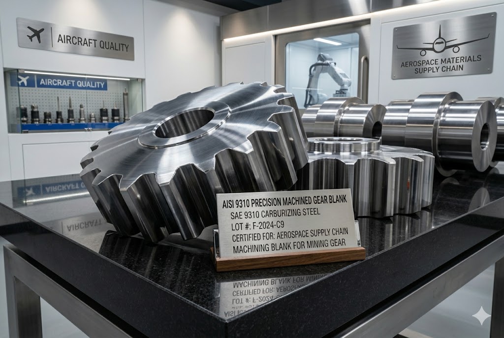
Aerospace Supply Chain — Forged Gear Blanks & Structural Components
Aerospace power transmission gears must sustain hundreds of millions of load cycles with near-zero tolerance for tooth root fatigue crack initiation. The challenge in thin-walled gear geometries is achieving through-hardening in the relatively thin tooth cross-section without overheating or distorting the adjacent bore or web sections. AISI 9310's high Ni-Cr-Mo hardenability combination allows the case-to-core transition to occur at the correct depth regardless of whether the section is a 15mm tooth or a 60mm bore wall — the grade does not require section-specific quench media or cooling rate adjustments. We supply AISI 9310 forged gear blanks and semi-finished components for use as upstream material in aerospace component supply chains, with material composition and testing to applicable aerospace material specifications.
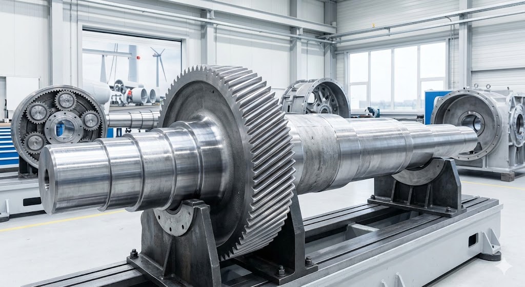
Wind Energy — Gearbox Pinion Shafts & Planet Gears
A wind turbine gearbox operates continuously for 20+ years, often in offshore or remote locations where unscheduled maintenance is extremely costly. The gears and shafts must sustain billions of load cycles, cope with torque reversals during gusts, and resist surface pitting from elastohydrodynamic contact stresses in the 1,500–2,500 MPa range. The specific risk in wind gearboxes is micropitting — a surface fatigue phenomenon that begins at the case-core boundary if the compressive residual stress distribution from carburizing is non-uniform. AISI 9310's Mo content suppresses austenite grain coarsening during long carburizing cycles, maintaining fine-grained case microstructure and uniform residual stress distribution — directly reducing micropitting initiation risk. Our AISI 9310 forged pinion shafts and planet gear forgings for wind gearbox applications are manufactured with controlled case depth profiles targeting the compressive residual stress peak at 0.15–0.25mm below the case surface.
Oil & Gas — Wellhead & Downhole Transmission Components
Downhole mud pump gear shafts, power swivel spline drives, and BOP actuator shafts face a specific combination of demands: they must resist abrasive wear from drilling fluid solids, absorb impact loads from stick-slip drilling dynamics, and maintain dimensional integrity in the presence of hydrogen sulfide — a gas that causes hydrogen embrittlement in high-strength steels above approximately 90 ksi (621 MPa) yield strength. AISI 9310 in the properly tempered condition can be specified at 125 ksi (862 MPa) yield strength or lower to remain below NACE MR0175 cracking susceptibility thresholds, while the carburized surface independently provides the wear resistance that the bulk material cannot supply at the lower yield strength condition. Upon specific customer request, our AISI 9310 forgings for sour service can be manufactured to meet NACE MR0175/ISO 15156 material hardness and heat treatment requirements, documented with applicable test reports.
Mining & Heavy Construction — Crusher Shafts & Excavator Slewing Rings
The eccentric shaft of a gyratory crusher handles impact energy equivalent to hundreds of tonne-force per revolution, with abrasive rock material in direct contact with the external bearing surfaces. The engineering compromise most materials face here is fundamental: increasing surface hardness for wear resistance decreases core toughness and increases fracture risk from impact — and vice versa. AISI 9310 breaks this compromise with its high-nickel core toughness: the core impact energy of a properly heat-treated 9310 shaft (typically 68–90 J Charpy at room temperature, 50+ J at −20°C) is substantially higher than comparable hardness grades such as 8620 or 4320, while the carburized surface achieves the same 58–62 HRC wear resistance. For excavator slewing bearing outer rings — large-diameter rolled rings in 9310 — the combination of circumferential grain flow from ring rolling and high core toughness produces a measurably lower failure rate in field service compared to fabricated or lower-alloy alternatives.
Cement, Metallurgy & Heavy Industry — Kiln Drive Pinion Shafts & Gear Rings
Rotary kiln pinion shafts and riding gear rings operate at very low speeds (0.5–5 RPM) but under extremely high sustained torque loads with significant thermal cycling as the kiln shell and support structure expand and contract. The dominant failure mode is bending fatigue at the tooth root, driven by misalignment stress from kiln shell deflection rather than purely contact stress. AISI 9310's deep case capability (carburize to 2.5mm effective depth for large-module gear rings) combined with high core strength (330–375 HBW after carburize-and-quench) provides adequate root bending strength even in module 30–50 gear rings where the loaded tooth root cross-section is substantial. Our standard supply for cement industry gear components includes both the forged gear blank and the finish-machined gear profile, with tooth hardness survey (point-to-point hardness across the tooth face, flank, and root) as part of the delivery documentation.
Railway & Heavy Transportation — Traction Drive Transmission Gears
Locomotive traction motor gears and heavy haul vehicle final drive planet gears operate on load spectra that include frequent high-torque acceleration cycles, steady-state cruise loads, and dynamic shock events from track irregularities. Railway standards typically require gear material certification to a specific fatigue strength grade, defined as the tooth root bending fatigue stress limit (in MPa) at 3×10⁷ cycles. AISI 9310 in the carburized-and-quenched condition consistently achieves tooth root bending fatigue stress limits of 450–550 MPa in representative gear test geometries — at the upper end of commercially available carburizing steel options. Our AISI 9310 forged gear blanks for railway applications are supplied with full material certification documentation suitable for submission to the railway system integrator's first-article inspection process.
Industrial Gearboxes & Power Generation
Beyond the specialized industries above, AISI 9310 forged gears, shafts, and rings are in continuous service across industrial gearboxes (planetary reducers, parallel shaft reducers, bevel gear sets), gas turbine accessory drives, gas compressor gear drives, large pump drive shafts, and sugar mill drive transmission components. Any application where the gear or shaft operates at module 6 or higher, pitch line velocity above 25 m/s, or contact stress above 1,200 MPa is a strong candidate for AISI 9310 rather than lower-alloy alternatives — and our engineering team can provide a material selection analysis for your specific application on request.
Quality Assurance & Inspection — Our Process from Billet to Shipment
Quality in forging is not a final inspection activity — it is a process control discipline. A forging that has been inadequately processed cannot be "inspected into compliance." The following sequence describes our quality gates for every AISI 9310 forging order, with the specific purpose of each step and what it prevents from reaching the customer.
Gate 1: Incoming Billet Verification
Every AISI 9310 billet lot received from the steel mill is sampled and independently re-analyzed in our OES (Optical Emission Spectrometer) laboratory before any production use. We verify all 10 elements in the ASTM A534 composition table against the mill certificate. Lots with any element outside specification are quarantined and returned. Billet surface condition is visually inspected for cracks, seams, and laps that could propagate into the finished forging. Heat number is stamped or engraved on each billet and maintained in traceability records throughout production.
Gate 2: Forging Process Records
Each forging operation is documented on a production traveller that records: billet heat number, furnace heating temperature and soak time, press tonnage applied per reduction pass, forging finish temperature (above which the steel remains in the hot working range), and achieved forging ratio. Any deviation from the approved forging procedure is flagged for engineering review before proceeding. The traveller travels with the part through all subsequent operations.
Gate 3: Post-Forge Dimensional Check & Visual Inspection
After forging and cooling, rough dimensions are measured against the forging drawing. Surface is inspected for forging laps, cracks, underfill, or scale inclusions. Parts failing visual inspection are either repaired (grinding within the drawing allowance) or rejected before entering the heat treatment queue — preventing wasted furnace capacity on non-conforming material.
Gate 4: Heat Treatment Cycle Documentation
Every heat treatment furnace run produces a time-temperature chart recorder output (or digital log for CNC furnaces) that is archived and supplied to the customer as part of the documentation package. Records include: furnace ID, load description, set points vs. actual temperatures at multiple thermocouple positions, ramp rates, soak times, quench media temperature, and operator sign-off. For carburizing cycles, carbon potential set point and probe readings throughout the cycle are included.
Gate 5: Mechanical Properties Testing
Test coupons machined from separately forged and heat-treated test bars (from the same heat and same process cycle as the production parts) are destructively tested to verify: tensile strength, yield strength, elongation, reduction of area, Charpy impact (when specified), and Brinell hardness. Results are reviewed against drawing requirements before production parts are released for finish machining.
Gate 6: Non-Destructive Testing (NDT)
NDT method choice is based on the part geometry and application requirements, specified in the drawing or customer technical requirement:
- Ultrasonic Testing (UT): Volume scan for internal discontinuities (voids, inclusions, segregation areas). Standard practice on all AISI 9310 forgings above 50mm cross-section carried out based on applicable standards. Acceptance criteria in accordance with drawing or industry standard (e.g. EN 10228-3, ASTM A388).
- Magnetic Particle Testing (MT): Surface and near-surface crack detection on ferromagnetic parts after final machining or grinding. Detects grinding cracks that may occur during abusive machining and any tight surface flaws missed by visual inspection.
- Liquid Penetrant Testing (PT): Surface discontinuity detection, used as an alternative to MT for complicated geometries or as a supplementary test where MT indicates further investigation.
- Hardness Survey: Brinell or Rockwell hardness tested at specified locations on each production forging (not just test coupons) to confirm heat treatment response is consistent across the lot.
Gate 7: Final Dimensional Inspection & CMM Report
100% dimensional inspection is performed on all important dimensions per the drawing. Complex machined parts are measured on our Coordinate Measuring Machine (CMM) with full dimensional report. Surface finish is verified with contact profilometer at all specified Ra locations.
Documentation Package (Standard with Every Order)
- Inspection and Test Plan (ITP) with customer-specific hold/witness points
- Mill test certificate with full ladle and product chemistry analysis (heat number traceable)
- Our in-house incoming inspection spectrometer re-test report
- Forging process traveller records
- Heat treatment time-temperature charts and parameter logs
- Mechanical properties test coupon report
- NDT reports (UT, MT, PT, hardness as applicable)
- CMM dimensional inspection report
- Certificate of Conformance (CoC) referencing drawing number, revision, and customer PO
- Packing list and shipping documentation
- EN 10204 Type 3.1 inspection certificate as standard; Type 3.2 (third-party witness) available on request
Frequently Asked Questions About AISI 9310 Forging Parts
AISI 9310 (UNS G93100) is a low-carbon nickel-chromium-molybdenum carburizing alloy steel standardized by the American Iron and Steel Institute. Its defining characteristic is an unusually high nickel content of 3.00–3.50%, which is approximately 3–5 times the nickel level found in common alternatives such as AISI 8620 (0.4–0.7% Ni) or AISI 4320 (1.65–2.00% Ni).
This high nickel level produces three engineering advantages that differentiate 9310 from other carburizing steels: (1) superior hardenability in large cross-sections — the Ni-Cr-Mo combination keeps the steel hardenable even in sections above 200mm, where lower-alloy grades would produce soft spots; (2) better low-temperature toughness — nickel lowers the ductile-to-brittle transition temperature, so that 9310 is suitable for sub-zero operating environments; (3) finer-grained, tougher martensite in the core after quench — the high Ni produces predominantly lath (not plate) martensite in the core, which is inherently more ductile at equivalent hardness. The result is a material that combines 58–62 HRC surface hardness with core impact toughness values (typically 68–90 J Charpy at room temperature) that lower-alloy carburizing steels cannot match.
AISI 9310 is primarily specified when an application simultaneously requires: (a) a very hard (58–62 HRC) wear-resistant surface to resist contact fatigue or abrasion, and (b) a tough, high-strength core to resist bending fatigue, impact, and shock loads — typically in section sizes too large for lower-alloy grades to achieve full through-hardening.
Specific applications that commonly require AISI 9310 over alternatives: aerospace-supply-chain gear blanks where section hardenability consistency is mandatory; wind turbine gearbox pinion shafts and planet gears operating at >1,500 MPa contact stress for 20+ year design lives; heavy mining crusher eccentric shafts above 200mm diameter where 8620 or 4320 cannot provide adequate core toughness at hardened surface conditions; locomotive traction gear sets requiring tooth root bending fatigue limits above 450 MPa; and industrial gearbox stages above module 20 where the tooth cross-section thickness requires deep hardenability. The selection criterion is straightforward: if the component's section size, fatigue requirement, or low-temperature service condition exceeds what AISI 8620 can deliver, AISI 9310 is the standard next choice.
After carburizing and hardening, the surface hardness of AISI 9310 reaches 58–62 HRC. The core hardness, measured at the center of the cross-section after quench and low-temperature temper, typically ranges from 300–380 HBW (approximately 33–41 HRC), depending on the specific reheat temperature, quench severity, and section thickness.
Case depth is specified as either "effective case depth" (ECD) — the depth at which hardness drops to HRC 50 or a specified value — or "total case depth" (TCD) — the total depth of carbon-enriched zone visible in metallographic section. ECD is more commonly used in gear engineering. For AISI 9310 gear applications, ECD is typically specified at 0.8–2.5mm depending on module size: smaller modules (4–8) use 0.8–1.3mm ECD; larger modules (12–25) use 1.5–2.5mm ECD. Case depth is verified by two methods: Vickers microhardness traverse (hardness measured at 0.1mm increments from surface inward on a metallographic cross-section) and visual metallographic examination of the case-to-core transition. We report both in our documentation. The case depth result from the actual production forging (not just test coupon) is required and reported for each lot.
The primary material standards applicable to AISI 9310 forgings are: ASTM A534 (bearing quality bar and rod, which also covers forging stock chemistry); AMS 6265 (bar and rod, forging stock — composition and processing requirements); and AMS 6267 (premium aircraft quality bar, with tighter cleanliness requirements). For forgings specifically, the material chemistry is governed by these standards, while the forging inspection requirements are typically covered by customer drawings or referenced inspection standards such as EN 10228-3 (UT) and EN 10228-1 (MT).
Our standard documentation package includes: mill test certificate with ladle and product chemistry (full heat traceability), our in-house OES re-test report, forging process records, heat treatment time-temperature logs, mechanical properties test coupon report (tensile, yield, elongation, Charpy if specified, hardness), NDT reports per applicable standards, dimension test report, and EN 10204 Type 3.1 inspection certificate. Type 3.2 (third-party surveyor witness) is available on request at additional cost. All documents reference the customer PO number, drawing number, and revision letter.
Yes — custom forging production to customer drawings is our main business model. To generate an accurate quotation and production plan, the following information is required: (1) 2D drawing or 3D model of the finished machined part (from which we derive the forging envelope and tooling requirements); (2) material specification, including grade and applicable standard; (3) heat treatment specification, including minimum hardness, case depth (if carburized), and test coupon requirements; (4) inspection requirements, including NDT methods, acceptance criteria, and any hold/witness points; (5) required quantity and requested delivery date; (6) applicable industry or customer-specific standards.
If any of the above are undefined or if your design is still in development, our engineering team can provide guidance on forging design optimization, achievable tolerances, and heat treatment capability — typically within 24 hours of receiving your drawing. We support both single-piece prototype production (1 piece minimum) and volume production of hundreds of pieces per month, with the same quality documentation standard for all quantities.
Our 6,300-ton hydraulic forging press handles single-heat AISI 9310 forgings from 30 kg to 30,000 kg (30 metric tons). Maximum forging length for shaft-type components is approximately 12 meters. For seamless rolled rings, the radial-axial ring rolling mill produces outer diameters from 300mm to 5,000mm, heights from 50mm to 1,200mm, and wall thicknesses from 50mm to approximately 1,000mm (OD/ID ratio ≥ 1.15).
For components at the large end of this range (single pieces above 15 tonnes), please note that lead time includes ingot procurement and potentially extended forging campaign scheduling. We recommend contacting us with your preliminary dimensions as early as possible in your project timeline for very large pieces, as ingot availability can affect schedule more than the forging and heat treatment operations themselves.
Yes. Our in-house CNC machining capability includes turning centers up to 3,000mm swing × 12,000mm between centers, vertical turning/milling up to 5,000mm diameter, 3/4/5-axis machining centers, and cylindrical, surface, and internal grinding. After carburize-and-harden, finish grinding is the standard process for bearing journals and gear datum bores.
Standard achievable tolerances after finish machining: IT6 on critical bearing journal diameters (e.g., H7 bore, k6 shaft), ±0.01mm on length between ground surfaces, flatness and parallelism to 0.02mm/100mm. Surface finish: Ra 0.4–0.8 µm on ground bearing surfaces; Ra 1.6–3.2 µm on turned and finished faces. Tighter tolerances and finer finishes are achievable for specific features — please specify on your drawing. All critical dimensions are verified on our CMM with a dimensional inspection report included in the delivery documentation.
Standard production lead time from drawing confirmation and material release to delivery of rough-machined and inspected AISI 9310 forgings is 20–35 days. Finish machining adds 7–14 days depending on complexity. The primary driver of lead time variation is: (1) billet/ingot procurement — standard cross-section billets are typically in stock or available within 5–7 days; oversized ingots for pieces above 15 tonnes may require 2–4 weeks to source; (2) furnace scheduling — carburizing cycles for deep case depths (2.0mm+) run 40–60 hours plus cooling and quench time; (3) part complexity — multi-step shafts with many features require more setups and machining time than simple cylinders.
For repeat orders with previously approved drawings and validated process parameters, lead times are typically reduced to 15–25 days. Expedited production is available for urgent requirements — please specify your required delivery date at inquiry so we can confirm feasibility and schedule before order placement. We will not accept a delivery commitment we cannot meet.
Yes — we accept single-piece prototype orders for AISI 9310 forgings with no minimum quantity restriction. The quality documentation package for a 1-piece prototype order is identical to that for a 500-piece production order: full chemistry certification, heat treatment records, mechanical test coupon report, NDT, and dimensional inspection. There is no "prototype exception" on documentation at Jiangsu Liangyi.
One practical consideration for prototype orders: because AISI 9310 heat treatment requires dedicated furnace time and test coupons, the per-piece cost for 1–3 pieces is substantially higher than for larger batches. If your project will ultimately require volume production, we recommend discussing the full anticipated volume at the prototype stage so we can plan material ordering and furnace scheduling to reduce cost on the follow-on production order. We have converted many single-prototype engagements into long-term supply agreements, and are happy to discuss long-term pricing structures from the first conversation.
This is the most common material selection question we receive. All three are Ni-Cr-Mo carburizing steels, but the Ni content differs dramatically: AISI 8620 contains 0.40–0.70% Ni, AISI 4320 contains 1.65–2.00% Ni, and AISI 9310 contains 3.00–3.50% Ni. This Ni difference drives three key selection criteria:
Section hardenability: In thin sections (<50mm), all three grades achieve full through-hardening and the performance difference is minimal. In sections above 100mm, 8620 begins to show soft core zones in the quenched-and-tempered condition; 4320 holds through-hardening to about 150mm; 9310 maintains full through-hardening to 200mm+ in most quench conditions. If your gear has a root circle diameter above 200mm, 9310 is the technically correct choice.
Core toughness at equivalent hardness: At equivalent core hardness (e.g., 310–350 HBW), 9310 consistently shows higher Charpy impact values than 8620 or 4320 due to the nickel stabilization of lath martensite microstructure. The practical implication is that 9310 shafts and gear cores can absorb more shock energy before fracture — important for crusher drives, railway applications, and marine gearboxes.
Cost: 9310 costs approximately 20–35% more per kg than 8620 due to the higher nickel alloy content. For applications where 8620 or 4320 can meet the design requirements, the premium is not justified. Our engineering team can help evaluate whether your specific application requires 9310 or can use a lower-alloy grade — we will recommend the lower-cost option when it is genuinely appropriate for the design.
Distortion during carburize-and-quench is the most common production quality issue in 9310 gear and shaft manufacturing, and it deserves a direct answer rather than a generic statement about "our expertise." The three root causes are: (1) asymmetric residual stress from forging or rough machining, which is "released" by the thermal cycle of carburizing; (2) non-uniform temperature distribution in the furnace load or quench tank, causing different sections to transform to martensite at different times and producing transformation strain mismatch; (3) geometric asymmetry — a part that is thick on one side and thin on the other will always distort more than a symmetric part, regardless of process quality.
Our process controls for distortion: (a) rough machining all features to within 0.5–1.5mm of finish before carburizing, to release machining-induced stress before the thermal cycle; (b) symmetrical fixturing and load positioning in the carburizing furnace to equalize atmosphere circulation; (c) agitated oil quench with controlled temperature (50–80°C) and consistent agitation to minimize quench non-uniformity; (d) cold press straightening after quench and before tempering for shaft-type parts showing >0.5mm runout. For high-precision gear blanks where distortion tolerance is below 0.3mm, we use fixturing dies during the oil quench phase, which physically constrains radial distortion during the martensite transformation. We do not guarantee zero distortion on carburized parts — no one honestly can — but we do guarantee dimensional compliance to drawing tolerances at final delivery.
Why Customers Choose Jiangsu Liangyi for AISI 9310 Forgings
There are many forging suppliers in China. The following points reflect what experienced procurement engineers and metallurgical engineers consistently cite when explaining why they work with us specifically — not generic marketing statements, but the specific operational details that matter in actual sourcing decisions.
- 27 Years of High-Alloy Forging Specialization (Established 1997): We are not a general metalworking company that also does some forging. Our entire production operation — equipment investment, staff training, quality system — is built around open die forging and ring rolling of high-alloy steels, including Ni-Cr-Mo grades like AISI 9310, 4340, 4140, and stainless and tool steels. This specialization means our engineers have seen and solved the specific challenges of AISI 9310 processing — distortion control, case depth consistency, and retained austenite management — across thousands of production lots over nearly three decades.
- Single-Source Accountability from Billet to Finished Part: Every operation — billet inspection, forging, heat treatment, machining, NDT, and documentation — is performed in our own facility, under our own ISO 9001:2015 quality system, with our own employed technicians. When a question arises about a heat treatment record or an UT indication, there is one phone number to call. We have seen what happens when machining is subcontracted to a second supplier, heat treatment goes to a third: quality chains break and documentation gaps appear. We do not operate that way.
- 6,300-Ton Press with CNC Position Control — Not Just Raw Tonnage: Large tonnage alone does not produce quality forgings. Our 6,300-ton press uses CNC-controlled stroke position and pressing speed, allowing the operator to execute precise reduction-per-pass sequences that achieve the targeted forging ratio without overworking or burning the steel surface layer. For AISI 9310 specifically, forging finish temperature control (staying above approximately 850°C) is critical to prevent surface cracking — our temperature monitoring during forging makes this visible and controllable, not guesswork.
- In-House Spectrometer Re-Testing of Every Billet Lot: Our OES (Optical Emission Spectrometer) laboratory re-tests every incoming AISI 9310 billet lot against the mill certificate — all 10 elements in the composition table. We have occasionally rejected lots where the mill certificate showed acceptable chemistry but our re-test identified specific elements slightly outside range. This in-house verification is the only reliable way to ensure the composition of what actually enters your part is what the documentation says it is.
- Transparent Engineering Communication: Our sales and technical teams communicate directly in English (and other languages on request) with quantitative, specific language — not vague assurances. When a tolerance is borderline, we say so and explain the options. When a process requirement is outside our demonstrated capability, we decline the order rather than promise what we cannot deliver. Customers from Europe, North America, and Australia consistently report that this communication style is the key differentiator from the typical experience with Chinese suppliers.
- Competitive Factory-Direct Pricing Without Middlemen: We quote and supply directly — no trading company or agent markup in our pricing structure. For reference, our AISI 9310 forging prices are typically 25–40% below equivalent European or North American forging sources for the same specification and quality level. We are transparent about pricing — if another supplier is quoting significantly lower than us, we will tell you what corners are likely being cut to achieve that price.
- Customers in 50+ Countries Across All Major Industrial Sectors: Our customer base is spread over Europe (Germany, Netherlands, UK, Italy, Spain), North America (USA, Canada), Australia, South Korea, India and South East Asia and consists of wind energy OEMs, cement plant equipment suppliers, mining machinery manufacturers, oil-field equipment manufacturers and industrial gearbox producers.Reference cases and general project descriptions are available on request for qualified customers under NDA.
Get Your Free Custom Quote for AISI 9310 Forgings
Your Reliable AISI 9310 Forging Partner in China
Welcome to send us your detailed drawings, material specifications, quantity requirements, and project standards for a free, competitive quote. Our professional team will get back to you with a tailored solution and detailed offer within 24 hours.
Request a Free Quote Contact UsContact Our Forging Experts
Company Name: Jiangsu Liangyi Co.,Limited
Email: sales@jnmtforgedparts.com
Phone & WhatsApp: +86-13585067993
Tel & Fax: +86-510-86107550
Official Website: www.jnmtforgedparts.com
Factory Address: Chengchang Industry Park, Jiangyin City, Jiangsu Province, China