Incoloy 903 (UNS N19903, Alloy 903) Forging Parts | Professional China Manufacturer
Jiangsu Liangyi Co.,Limited is an ISO 9001:2015 certified open die forging manufacturer producing components in compliance with PED 2014/68/EU, ASME BPVC, and API application requirements based in Jiangyin City, Jiangsu Province, China. Since our founding in 1997, we have accumulated more than 28 years of specialized manufacturing experience in nickel-iron-cobalt superalloy forgings, with Incoloy 903 (UNS N19903, Alloy 903) one of our main specialty products. Our 80,000 m² facility has a dedicated Alloy 903 forging line with 5,000-ton and 12,500-ton hydraulic presses, a CNC radial-axial ring rolling mill for rings up to OD 3,500 mm, and heat treatment furnaces qualified to AMS 2750 Class 5. We supply custom Alloy 903 open die forgings and seamless rolled rings from 30 KG to 30,000 KG per piece to customers in nuclear power, turbomachinery, oil & gas, aerospace, and defense in more than 50 countries. Our total annual forging capacity across all alloys is 120,000 metric tons.
📋 Incoloy 903 Forging — Key Technical Facts at a Glance
✅ Expert Verified: All technical data on this page is drawn from our internal manufacturing specifications and cross-checked against AMS 5664, AMS 5667, and ASTM B637 by our metallurgical team. Last reviewed June 2025.
Why Choose Jiangsu Liangyi for Incoloy 903 Forgings
Incoloy 903 is a demanding alloy. Its performance depends heavily on melting quality, forging reduction ratio, and heat treatment control. Without the right process discipline, you get inconsistent mechanical properties, niobium micro-segregation, and dimensional problems in service. Here is what sets us apart from general nickel alloy suppliers:
28+ Years of Alloy 903 Specialization
We have been producing Incoloy 903 forgings continuously since 1997. Our team has worked through more than 340 distinct Alloy 903 part numbers across nuclear, turbine, oil & gas, and aerospace applications. Every production parameter — from billet heating temperature (1,120–1,150°C) to final forging temperature window — is set specifically for UNS N19903 to prevent hot cracking and keep grain size uniform.
Controlled Deformation Ratio ≥ 4:1
For Incoloy 903, we maintain a minimum forging reduction ratio of 4:1 on all forgings to ensure complete breakdown of the as-cast dendritic structure, uniform niobium distribution, and consistent ASTM grain size of 3–5. This is a critical internal specification we enforce beyond what most customers specify — because under-forged Alloy 903 will show lower fatigue life and unpredictable CTE behavior even if it passes static mechanical testing.
Full VIM+VAR / VIM+ESR+VAR Traceability
We work exclusively with premium melt sources using double (VIM+VAR) or triple (VIM+ESR+VAR) vacuum remelting routes. Every heat of Alloy 903 we use carries a complete chemical analysis, ingot map, and segregation test report. Our incoming material inspection includes spectrographic analysis and macroetch testing per ASTM A604 before any forging begins — we reject material that does not meet our internal chemical windows, which are tighter than the published specification.
AMS 2750 Class 5 Heat Treatment Furnaces
Our Alloy 903 heat treatment furnaces are qualified to AMS 2750 Class 5 (±8°C temperature uniformity). All three stages — solution treatment, first aging, second aging — run on automated PLC-controlled profiles, and every batch gets a furnace load chart with thermocouple records at ±1°C resolution. That level of control matters: a ±15°C variation during first aging can move yield strength by 50–80 MPa.
100% Volume Ultrasonic Testing (UT)
Every piece of Alloy 903 forging we deliver undergoes 100% full-volume ultrasonic testing per SEP 1923, inspection level D3/D2, using calibrated dual-crystal search units. Our UT sensitivity is set to detect reflectors ≥ 2 mm flat-bottom hole equivalent — well beyond the minimum requirement for most nuclear and turbine applications. We maintain UT calibration records traceable to national standards for every inspection instrument used on your order.
30 KG–30,000 KG in One Factory
Our facility handles the complete weight range from prototype-scale rings (30 KG) to massive single-piece turbine casings (30,000 KG) in a single integrated production flow. This eliminates subcontracting risk and ensures consistent quality standards across all weight classes. For projects requiring multiple components at different sizes — for example, a valve body at 200 KG and its mating ring at 800 KG — we produce both in the same facility under the same quality system.
Tighter-Than-Standard Chemical Windows
Based on 28 years of production data, we have established internal chemistry windows that are narrower than the published UNS N19903 specification at critical elements. Specifically, we target niobium at 2.70–3.20 wt% (vs. published 2.40–3.50 wt%), titanium at 1.20–1.65 wt%, and we control carbon at ≤ 0.03 wt% to minimize grain boundary carbide formation that can degrade notch sensitivity. This internal practice is not visible in our MTC but is a core reason our Alloy 903 forgings consistently outperform specification minima.
Global Delivery with Full Document Package
We export to 50+ countries with experience preparing the documentation packages required under European PED, US ASME, Middle Eastern ARAMCO, and Australian AS/NZS procurement specifications. Every shipment is accompanied by a complete document package: EN 10204 3.1 or 3.2 MTC, heat treatment records, full NDT reports, dimensional inspection report, and a certificate of conformance. Fumigated wooden crates with ISPM 15 phytosanitary certification are standard for sea freight.
Incoloy 903 (UNS N19903) Forged Products We Supply
We manufacture the full range of Incoloy 903 wrought product forms by open die forging and seamless ring rolling. All products are made from vacuum-remelted ingots with full dimensional, metallurgical, and NDT traceability. We work from customer drawings — we do not carry stock inventory.
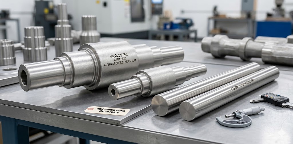
Incoloy 903 Forged Bars, Rods & Shafts
Our Alloy 903 forged bars are produced from VIM+VAR ingots with a minimum reduction ratio of 5:1, delivering a fully wrought microstructure with refined grain size throughout the cross-section. We supply round bars, flat bars, square bars, hexagonal bars, step shafts, gear shafts, and custom-profile rods in a wide dimensional range:
| Product Form | Dimensional Range | Weight Range | Typical Applications |
|---|---|---|---|
| Round Bar (Forged) | Ø50 mm – Ø600 mm | 30–8,000 KG | Valve stems, shaft blanks, fastener stock |
| Flat Bar / Block | T50–300 mm × W100–1,000 mm | 50–5,000 KG | Gage block blanks, ordnance hardware, structural parts |
| Step Shaft | Max. OD Ø600 mm, length up to 3,000 mm | 100–12,000 KG | Turbine shafts, compressor shafts, pump shafts |
| Gear Shaft / Pinion | Per customer drawing | 50–6,000 KG | Gearbox shafts, transmission components |
All forged bars are machined to rough-turned or black forged condition per customer specification, with straightness tolerance ≤ 1.5 mm/m as standard. Heat treatment in the precipitation hardened condition is standard; solution-annealed-only supply is available upon request for customers performing their own aging.
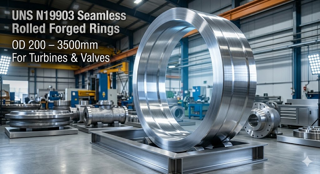
UNS N19903 Seamless Rolled Rings
Our CNC radial-axial ring rolling mill is specifically calibrated for Alloy 903, with special attention to rolling temperature control (900–1,050°C working range) and inter-pass cooling management to prevent excessive grain growth. We produce seamless rolled rings in the following configurations:
| Ring Type | OD Range | Wall Thickness | Height Range |
|---|---|---|---|
| Flat Ring (Straight Profile) | OD 200–3,500 mm | 20–400 mm | 30–600 mm |
| Contoured / Profiled Ring | OD 300–2,000 mm | Variable (per drawing) | 50–500 mm |
| Gear Ring (External/Internal) | OD 400–2,500 mm | 50–350 mm | 80–400 mm |
| Labyrinth Seal Ring | OD 200–1,500 mm | 15–80 mm | 20–200 mm |
| Bearing Ring Blank | OD 200–1,000 mm | 20–150 mm | 30–200 mm |
Seamless rolled ring forgings achieve superior grain flow alignment compared to fabricated weldments or flame-cut plate rings. For rotating components such as turbine casings and seal rings, the continuous circumferential grain flow provides 20–35% improved fatigue resistance in the hoop direction relative to alternative manufacturing methods.
Alloy 903 Forged Discs, Hubs & Impellers
Forged Incoloy 903 discs are manufactured with controlled upset forging to maximize radial grain flow, which is the critical direction for turbine disc and impeller applications where centrifugal stress acts radially outward. We supply turbine discs, pump impellers, compressor wheel blanks, flange discs, cover plates, and pressure vessel heads in the following size range:
- Diameter range: 200 mm – 2,500 mm
- Thickness range: 30 mm – 500 mm
- Weight range: 50 KG – 15,000 KG
- Profile: flat, hub-contoured, stepped, or custom per drawing
All discs undergo mandatory UT inspection per ASTM E2375 or customer-specified standard, with grain size confirmation per ASTM E112 available on request. For nuclear-grade disc forgings, we can additionally supply ACCP (Authorized Code Stamp Certifying Personnel) involvement documentation.
Alloy 903 Forged Hollow Components: Sleeves, Shells & Housings
Our open die forging with mandrel process produces Alloy 903 forged hollows — including cylindrical shells, pump casings, compressor barrels, valve bodies, tube shells, and bearing housings — with superior dimensional accuracy and uniform wall thickness compared to machined-from-solid billets. This approach reduces raw material consumption by 30–50% for large hollow components and produces better grain flow perpendicular to the axial direction.
- OD range: 200 mm – 1,800 mm
- Wall thickness: 20 mm – 300 mm
- Length/height: 100 mm – 2,500 mm
- Weight: 50 KG – 10,000 KG
UNS N19903 Forged Tubes, Tube Sheets & Pressure Vessel Components
For heat exchanger and pressure vessel applications, we supply Alloy 903 tube sheet forgings, baffle plates, channel flanges, nozzle forgings, and piping barrels. Tube sheet forgings for high-pressure shell-and-tube heat exchangers represent one of our highest-volume applications, where the alloy's dimensional stability under thermal cycling is critical for maintaining tube-to-tubesheet joint integrity over decades of service.
- Tube sheets: OD 300–2,200 mm, thickness 40–400 mm
- Nozzle forgings: DN 50–DN 600, per ASME B16.9 or customer drawings
- Flanges: per ASME B16.5 / EN 1092-1, Class 150 through Class 2500
- Full material documentation meeting ASME BPVC Section VIII material requirements available
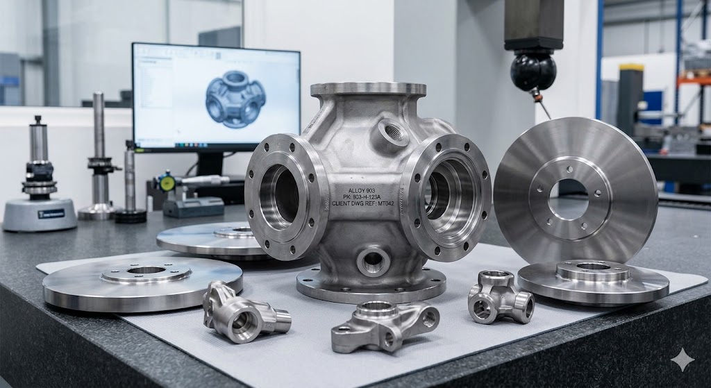
Incoloy 903 Custom Complex Forgings
Beyond standard product forms, we have significant experience in producing complex near-net-shape Alloy 903 forgings from customer drawings — including asymmetric housings, multi-tier stepped components, and precision-forged preforms for aerospace structural parts. Our engineering team performs forging process simulation (die design and material flow analysis) for complex parts before committing to tooling, which reduces development iterations and lead time for new components.
Incoloy 903 (UNS N19903): Metallurgy, Properties & Why They Matter
What is Incoloy 903? Incoloy 903 (UNS N19903, Alloy 903) is a precipitation-hardenable nickel-iron-cobalt superalloy built for applications that need a low, stable coefficient of thermal expansion (CTE) combined with high strength at service temperatures up to about 650°C (1,200°F). It was originally developed by Special Metals Corporation (now part of Precision Castparts Corp.) and has been in industrial use since the late 1970s. Its main advantage is a CTE that stays nearly constant at 7.0–8.5 μm/m·°C across the -200°C to +430°C range. Inconel 718, by comparison, runs 13–14 μm/m·°C — almost double — so 903 holds its dimensions far better across a wide thermal cycle.
The Role of Each Alloying Element in Incoloy 903
The table below explains what each alloying element does in Alloy 903 — useful context for heat treatment selection and predicting service behavior:
| Element | Content Range (wt%) | Our Internal Target (wt%) | Metallurgical Function |
|---|---|---|---|
| Nickel (Ni) | 36.0 – 40.0 | 37.0 – 39.5 | Primary austenite stabilizer; controls CTE through Invar-type effect. Higher Ni within range slightly increases CTE — targeting mid-range balances CTE control with corrosion resistance. |
| Iron (Fe) | Balance (~35–38%) | Balance | Base element contributing to the low-expansion Invar effect in combination with Ni and Co. Fe content directly controls the Curie temperature and the temperature range over which the CTE remains constant. |
| Cobalt (Co) | 13.0 – 17.0 | 14.0 – 16.0 | Extends the temperature range of the controlled-expansion behavior beyond what Ni-Fe alone achieves. Co also increases the solvus temperature of strengthening precipitates, improving high-temperature strength retention and creep resistance up to 650°C. |
| Niobium (Nb) | 2.40 – 3.50 | 2.70 – 3.20 | Primary strengthening precipitate — forms Ni₃Nb (γ″ phase) and (Ni,Co,Fe)₃Nb intermetallics during aging. Nb is the most potent strengthener in this alloy; our tighter internal window avoids both under-strengthening (low Nb) and Laves phase embrittlement (excess Nb after high-temperature exposure). |
| Titanium (Ti) | 1.00 – 1.85 | 1.20 – 1.65 | Forms Ni₃Ti (η phase) and contributes to γ′ strengthening. Ti also promotes solid-solution strengthening and refines grain boundary carbide morphology. Excess Ti above 1.85% can shift precipitation sequence and reduce ductility. |
| Aluminum (Al) | 0.30 – 1.15 | 0.40 – 0.90 | Contributes to γ′ (Ni₃Al) precipitation hardening and improves high-temperature oxidation resistance through formation of a protective Al₂O₃ sub-scale. Al is absent in the related Alloy 907, where its removal improves stress corrosion cracking resistance in hydrogen-containing environments. |
| Silicon (Si) | ≤ 0.50 | ≤ 0.30 | Residual element from deoxidation. Above 0.50%, Si promotes σ-phase and Laves phase formation during long-term high-temperature exposure, which significantly embrittles the alloy. Our tighter limit provides additional safety margin for components with long design lives. |
| Carbon (C) | ≤ 0.06 | ≤ 0.03 | Forms MC carbides (NbC, TiC) that pin grain boundaries and resist grain growth during hot working. However, excess carbon above our internal limit promotes continuous grain boundary carbide films that impair notch sensitivity and fatigue crack initiation resistance. |
| Manganese (Mn) | ≤ 0.50 | ≤ 0.30 | Residual deoxidizer. Minimized to reduce risk of MnS inclusions that can act as fatigue crack initiation sites in high-cycle fatigue applications. |
Physical Properties of Incoloy 903 (UNS N19903)
The physical properties below are what make Alloy 903 the right choice when dimensional stability under temperature change matters. Values are from our internal testing records:
| Physical Property | Value | Temperature Condition |
|---|---|---|
| Density | 8.19 g/cm³ (0.296 lb/in³) | Room temperature (20°C) |
| Melting Range | 1,340–1,400°C (2,444–2,552°F) | Solidus to liquidus |
| Coefficient of Thermal Expansion (CTE) | 7.0 μm/m·°C | 20°C to 100°C (68°F to 212°F) |
| Coefficient of Thermal Expansion (CTE) | 7.7 μm/m·°C | 20°C to 200°C (68°F to 392°F) |
| Coefficient of Thermal Expansion (CTE) | 8.1 μm/m·°C | 20°C to 430°C (68°F to 806°F) |
| Elastic Modulus (Young's Modulus) | 146.8 GPa (21,290 ksi) | 0°C (32°F) |
| Elastic Modulus (Young's Modulus) | 144.1 GPa | 100°C (212°F) |
| Elastic Modulus (Young's Modulus) | 138.6 GPa | 300°C (572°F) |
| Poisson's Ratio | 0.226 | 25°C (77°F) |
| Thermal Conductivity | 12.7 W/m·K | Room temperature |
| Electrical Resistivity | 1.01 μΩ·m | Room temperature |
| Specific Heat Capacity | 419 J/kg·K | Room temperature |
The real advantage of Incoloy 903 is not just a low CTE — it is that the CTE stays nearly constant across a wide temperature range. Most alloys show rising CTE as temperature increases. Alloy 903's CTE shifts by less than 1.5 μm/m·°C between 20°C and 430°C. This means a precision component — such as a turbine seal ring or a reactor pump casing — maintains predictable dimensional change across its entire thermal cycle, making tight clearance design possible. In gas turbine applications, a 1 μm/m·°C difference in CTE between the casing and the blade tip can translate to 0.5–2 mm tip clearance variation, directly affecting stage efficiency and life.
Mechanical Properties of Incoloy 903 (Precipitation Hardened Condition)
The following properties represent the guaranteed minimum values for our Alloy 903 forgings delivered in the standard three-stage precipitation hardened condition. Mill test certificate values consistently exceed these minimums in our production — actual average values from our 2024 production batch testing are shown where available:
| Mechanical Property | Specification Minimum | Typical Achieved Values (representative) | Test Standard |
|---|---|---|---|
| Tensile Strength (UTS) | 1,310 MPa (190,000 psi) | 1,380 ± 45 MPa | EN ISO 6892-1 / ASTM E8 |
| Yield Strength (0.2% Proof Stress) | 1,100 MPa (160,000 psi) | 1,155 ± 40 MPa | EN ISO 6892-1 / ASTM E8 |
| Elongation at Break (A₅) | ≥ 14% | 17.5 ± 2.2% | EN ISO 6892-1 |
| Reduction of Area | ≥ 18% | 24.3 ± 3.1% | EN ISO 6892-1 |
| Hardness (HRC) | 38–48 HRC | 42 ± 2 HRC | ASTM E18 |
| Charpy Impact (room temperature) | ≥ 20 J | 34 ± 6 J | EN ISO 148-1 |
| Elastic Modulus (0°C) | 146.8 GPa | 146.8 ± 1.5 GPa | Internal, strain gauge method |
| Poisson's Ratio (25°C) | 0.226 | 0.228 | Internal, strain gauge method |
| Grain Size (ASTM) | ≤ ASTM 3 | ASTM 3–5 (average 4) | ASTM E112 |
Incoloy 903 contains aluminum (0.30–1.15 wt%), which, unlike in Alloy 907 and 909, increases susceptibility to hydrogen-assisted stress corrosion cracking (HASCC) in environments containing H₂S, cathodic protection, or high-pressure hydrogen. For applications involving hydrogen-containing process streams, sour gas service (NACE MR0175 environments), or external cathodic protection systems, we recommend discussing whether Alloy 907 (Al-free variant) or Alloy 909 (Co-free, Al-free variant) is more appropriate. Our engineering team can assist with alloy selection at no charge.
Industry Applications & Proven Project Cases
Below are the industries we work in, the components we make for each, and real project cases from our production history — all based on actual orders we have delivered.
Nuclear Power — Reactor Coolant Systems
Nuclear power has the strictest requirements for material traceability, dimensional precision, and documentation of any sector we work in. Incoloy 903 is selected for reactor coolant system components primarily because its controlled thermal expansion allows designers to maintain precise clearances and sealing geometry across the full temperature cycle from cold shutdown (25°C) to full-power operation (280–320°C for PWR systems). Components we manufacture include:
- Reactor Coolant Pump (RCP) Rotor Impellers and Pump Casings — operating continuously in 280°C high-pressure primary coolant, where dimensional stability determines pump hydraulic efficiency over a 40-year design life
- Containment Vessel Penetration Seal Flanges — where the sealing surface geometry must be maintained across thermal transients without permanent set
- Control Rod Drive Mechanism (CRDM) Housing Components — requiring tight bore tolerances maintained at operating temperature
- Primary Circuit Valve Bodies and Bonnets — for isolation valves in the primary coolant loop, requiring zero-leakage performance at 160 bar
Gas Turbine & Steam Turbine — Casings, Discs & Valve Components
Gas turbines and steam turbines go through the most severe thermal cycling of any industrial system — a large-frame gas turbine can go from cold start to full load in under 10 minutes, with temperature swings above 500°C in the hot section. In standard high-CTE alloys, this causes seal gap variation and accelerated wear. Alloy 903's stable CTE keeps those gaps under control. We manufacture a full range of turbine forgings:
- Turbine Casings (LPT 1st–3rd Stage) — split-line flanged ring and shell forgings where maintaining the parting-face flatness across thermal cycles is critical for steam/gas sealing
- Turbine Discs and Blisks (Bladed Disk) — where hoop-direction fatigue life under centrifugal loading determines disc replacement intervals
- Main Stop Valve (MSV) / Governor Valve (GV) / Control Valve (CV) Seat Rings and Spindles — where seat-to-spindle contact geometry under thermal cycling determines valve leakage rate
- Labyrinth Seal Rings and Guide Rings — where the clearance between rotating and stationary labyrinth teeth must be maintained to within 0.1–0.3 mm at operating temperature
- Steam Chest and Valve Chest Forgings — high-pressure castings substituted with forgings for improved creep resistance and dimensional stability
Oil & Gas — High-Pressure Valve Components
In oil and gas, Alloy 903 is mainly used in high-integrity valve components where zero-leakage sealing has to hold across the full temperature range of well operations (from -30°C subsea to +200°C in high-pressure gas processing). What makes it better than conventional high-strength steels here is its stress relaxation resistance — it holds preload in bolted joints and valve springs without creeping over time. Components we supply include:
- Valve balls and seats for H-type two-way and one-way back pressure valves (ANSI 600 through ANSI 2500 class)
- Valve bonnets and valve bodies for gate valves, ball valves, and check valves per API 6A
- Valve stems, valve closures, and valve seat rings requiring NACE MR0175 documentation (consult us regarding H₂S service suitability for 903 specifically)
- Wellhead component forgings per API Spec 6A and API Spec 17D for subsea applications
- Spring components and preload elements where stress relaxation over years of service must be minimized
Centrifugal Compressor & Industrial Pump Industry
Centrifugal compressors in process gas service combine high rotational speeds (up to 25,000 RPM for small frames), process temperatures from cryogenic to 350°C, and tight impeller-to-casing clearances that directly affect efficiency and recycle leakage. When the working fluid temperature or the suction-to-discharge temperature differential is large enough that conventional materials shift dimensionally, Alloy 903 is the right choice for impellers, balance drums, and thrust bearings. We supply:
- Shrouded and open impeller blanks (pre-machined forging) for 3D-machined impellers, diameter 200–1,200 mm
- Balance drum forgings for multi-stage centrifugal compressors
- Bearing housing and thrust collar forgings with tight bore tolerances
- Pump shaft and impeller hub forgings for high-temperature boiler feed pump applications
- Suction/discharge nozzle forgings for API 617 compressor casings
Heat Exchanger & Pressure Vessel — Tube Sheets & Shell Components
Alloy 903 is used in heat exchanger tube sheets when the tube bundle and shell materials have very different CTEs, and the resulting differential expansion at operating temperature would crack conventional tube-to-tubesheet joints. A common example is a heat exchanger with Incoloy 800H tubes (CTE ≈ 16 μm/m·°C) in an Alloy 903 tube sheet, where the sheet's lower CTE reduces differential expansion stress at the expanded tube joint during thermal cycling. We manufacture:
- Heat exchanger tube sheets, OD 300–2,200 mm, thickness 40–400 mm, with documentation packages meeting ASME BPVC Section VIII requirements
- Shell forgings and flanged cylinder shells for pressure vessels rated to Class 600–2500
- Channel flanges and nozzle forgings per ASME B16.5 and customer drawings
- Baffle plates and support ring forgings for floating-head shell-and-tube heat exchangers
Aerospace, Defense & Precision Instrumentation
Aerospace and defense push dimensional stability to the limit. Rocket engine thrust chambers have to hold their geometry through thermal shock from cryogenic fuel temperatures to 3,000°C combustion products in milliseconds. Precision gage blocks need to stay calibrated across ordinary lab temperature swings. Alloy 903 handles both. We manufacture:
- Rocket engine thrust chamber structural ring forgings and mounting flange forgings
- High-performance precision coil spring blanks and Belleville washer stock for dimensionally critical spring assemblies
- Precision gage block blanks and reference standard body forgings for metrology equipment
- Ordnance component forgings where dimensional stability under storage temperature variation is a specification requirement
- Gyroscope housing forgings and inertial navigation system structural components
Heat Treatment of Incoloy 903: Process, Metallurgy & Critical Parameters
Why Incoloy 903 Requires a Three-Stage Heat Treatment
Incoloy 903 gets its strength from precipitation hardening — not from quenching and tempering. During aging, fine coherent precipitates form in the austenitic matrix: primarily γ″ (Ni₃Nb, body-centered tetragonal) and γ′ (Ni₃(Al,Ti), face-centered cubic), the same phases that strengthen Inconel 718 and Waspaloy. Each of the three heat treatment stages has a specific metallurgical job, and all three need to be done correctly to hit the final properties.
Solution Treatment: 844°C (1,550°F) / 1 hour / Water Quench
What it does: The solution treatment dissolves all previously formed precipitates back into solid solution in the austenite matrix, erasing any prior precipitation history and creating a uniform supersaturated solid solution from which precipitation can proceed in a controlled manner during subsequent aging. The temperature of 844°C is selected to be above the γ″ and γ′ solvus temperatures for this alloy's composition (approximately 815–830°C) but below the grain coarsening temperature. Critical parameter — quench rate: Water quenching is mandatory (not air cooling) to suppress precipitation during cooling. If the cooling rate falls below approximately 50°C/s through the 700–850°C range, coarse γ″ particles begin to form heterogeneously at grain boundaries, which creates a soft zone that persists through subsequent aging and reduces final strength by 5–12%. We use dedicated polymer-quench tanks with controlled agitation to ensure consistent quench rates for large forgings where natural water quench rates might be marginal.
First Aging: 719°C (1,325°F) / 8 hours / Controlled Furnace Cooling
What it does: The first aging treatment nucleates and grows the primary strengthening precipitates (γ″ and γ′) to a size that provides peak strength contribution. At 719°C, the precipitation kinetics are rapid enough to achieve full nucleation within 2–3 hours, with the subsequent 5–6 hours of hold time growing the precipitates to their optimal coherent size (approximately 15–30 nm). Critical parameter — temperature uniformity: A ±15°C deviation from the 719°C set point shifts the precipitate size distribution significantly — too high and precipitates coarsen beyond the coherency limit (overaging), too low and they remain undersized (underaging). Either deviation reduces tensile strength by 40–80 MPa below specification. This is why our AMS 2750 Class 5 furnaces are mandatory — Class 6 or lower (±14°C uniformity) is technically insufficient for reliable Alloy 903 processing. Cooling after first aging: Controlled furnace cooling at 2–5°C/min maintains the precipitate structure formed during aging while allowing internal stress relief. Rapid cooling at this stage would lock in thermal stresses that can cause dimensional distortion during subsequent machining.
Second Aging: 622°C (1,150°F) / 8 hours / Air Cool
What it does: The second (lower-temperature) aging step serves two functions: it nucleates a second, finer generation of γ′ precipitates in regions not yet saturated by first-age precipitation, and it stabilizes the grain boundary chemistry by completing the segregation of carbon to form discrete MC carbides rather than continuous grain boundary carbide films. The result is a bimodal precipitate distribution — coarser γ″/γ′ from first aging plus finer γ′ from second aging — that provides both high strength (from the coarse precipitates) and good ductility (from the fine, coherent secondary γ′). Why two aging temperatures rather than one: A single-temperature aging at either 719°C or 622°C alone would not achieve the combination of strength and ductility required by the specification. Single-temperature aging at 719°C produces higher strength but lower elongation (8–11%); at 622°C alone, full precipitation takes over 20 hours and grain boundary carbide morphology is less favorable. The two-stage process is the metallurgically optimized solution that achieves specification targets reliably.
In our experience reviewing customer rejections from other Alloy 903 suppliers, the most common cause of below-specification tensile strength is inadequate quenching after solution treatment in large cross-section forgings (diameter > 200 mm). Many suppliers water-quench large forgings in still tanks without agitation, resulting in a quench rate in the core of a 300 mm diameter bar of only 20–35°C/s — below the 50°C/s minimum required. The result is a "soft core" effect where core tensile strength can be 80–120 MPa below the rim. Our forced-flow quench system maintains core quench rates ≥ 55°C/s for forgings up to 500 mm diameter, verified by embedded thermocouples in qualification runs.
Mechanical Properties After Standard Heat Treatment
The table below shows guaranteed minimum values. Every forging we deliver is tested from prolongation pieces cut from each piece (longitudinal direction), with additional transverse specimens for forgings over 1,500 KG. Full MTC (EN 10204 3.1 or 3.2) covers all test results:
| Mechanical Property | Specification Minimum | Typical Achieved Values (representative) |
|---|---|---|
| Tensile Strength (UTS) | 1,310 MPa (190,000 psi) | 1,380 ± 45 MPa |
| Yield Strength (0.2% Proof Stress) | 1,100 MPa (160,000 psi) | 1,155 ± 40 MPa |
| Elongation at Break (A₅) | ≥ 14% | 17.5 ± 2.2% |
| Reduction of Area | ≥ 18% | 24.3 ± 3.1% |
| Hardness (Rockwell C) | 38–48 HRC | 42 ± 2 HRC |
| Elastic Modulus (0°C) | 146.8 GPa (21,290 ksi) | 146.8 ± 1.5 GPa |
| Poisson's Ratio (25°C) | 0.226 | 0.228 |
Alloy 903 vs. 907 vs. 909 vs. Inconel 718: Which Alloy Is Right for Your Application?
Incoloy 903 is one of a family of controlled-expansion nickel-iron-cobalt alloys. Engineers frequently need to choose between Alloy 903, 907, 909, and Inconel 718 based on application-specific requirements. The table below is based on our experience manufacturing all four alloys. We will tell you which one suits your application, even if that turns out not to be Alloy 903.
| Property / Factor | Incoloy 903 (UNS N19903) | Incoloy 907 (UNS N19907) | Incoloy 909 (UNS N19909) | Inconel 718 (UNS N07718) |
|---|---|---|---|---|
| Alloy System | Ni-Fe-Co (Ni 38%, Co 15%, Fe bal.) | Ni-Fe-Co (Ni 38%, Co 13%, Fe bal., no Al) | Ni-Fe-Co (Ni 38%, Co-free, Fe bal., no Al) | Ni-Fe-Cr (Ni 50–55%, Cr 17–21%) |
| CTE (20–430°C) | 7.0–8.5 μm/m·°C (constant) | 7.0–8.5 μm/m·°C (constant) | 7.0–8.5 μm/m·°C (constant) | 13.0–14.5 μm/m·°C (rising) |
| Tensile Strength (PH) | ≥ 1,310 MPa | ≥ 1,275 MPa | ≥ 1,275 MPa | ≥ 1,276 MPa (AMS 5664) |
| H₂S / Hydrogen SCC Resistance | Lower (Al present promotes SCC) | Higher (Al-free design) | Higher (Al-free, Co-free) | Good (Cr-containing) |
| Oxidation Resistance | Good (Al₂O₃ sub-scale to ~650°C) | Moderate (no Al sub-scale) | Moderate (no Al or Co) | Excellent (Cr₂O₃ scale to ~980°C) |
| Max. Service Temperature | ~650°C (1,200°F) | ~650°C (1,200°F) | ~650°C (1,200°F) | ~700°C (1,292°F) |
| Machinability | Moderate (work hardens rapidly) | Moderate | Moderate | Moderate (standard nickel alloy) |
| Cobalt Content | 13–17% Co (nuclear activation concern) | 13% Co (same concern) | Cobalt-free (preferred for nuclear with irradiation near workers) | Cobalt-free |
| Raw Material Availability | Moderate (specialized alloy) | Moderate (slightly less available than 903) | Good (growing availability) | Excellent (high global stock) |
| Best-Fit Applications | Turbine casings, precision springs, gage blocks, rocket structures, non-H₂S valve components | Sour gas valve components, H₂S-containing environments, downhole tools | Cost-sensitive controlled-expansion applications, cobalt-restricted environments | Broad high-temperature structural applications, does not require low CTE |
If your application requires controlled low CTE and is not in H₂S or cathodic protection service, Incoloy 903 is the highest-strength option in this alloy family with the best-documented service history in turbine and nuclear applications. If H₂S or hydrogen charging is present, specify Alloy 907. If cobalt activation in nuclear environments is a regulatory concern, specify Alloy 909. If low CTE is not required and higher service temperature capability is the priority, Inconel 718 is the better choice. Contact our engineering team if you need assistance making this selection for your specific project — we manufacture all four alloys and have no preference bias.
Why Forging is the Superior Manufacturing Method for Incoloy 903 Components
Incoloy 903 components can in principle be produced by casting, powder metallurgy, or forging. For structural, pressure-retaining, and rotating applications, forging is almost universally specified, and for good technical reasons that are specific to this alloy's behavior:
Elimination of Casting Segregation — Critical for Alloy 903
Alloy 903's precipitation hardening response depends on the local niobium concentration. When this alloy is cast, niobium segregates strongly during solidification — it is the last element to solidify and concentrates in interdendritic regions at 1.4–1.8× the nominal composition. This means a nominally 3.0 wt% Nb alloy will have core regions at 2.0% Nb and interdendritic regions at 4.5% Nb in the as-cast state. Even after homogenization, this segregation is only partially reduced. The consequence for mechanical properties is significant: interdendritic high-Nb regions form Laves phase during aging (instead of the desired γ″), which has essentially zero strengthening contribution and can act as crack initiation sites. Our forging process, using reduction ratios of ≥ 4:1, mechanically disrupts the dendritic network and homogenizes the niobium distribution to within ±0.15 wt% of nominal across the entire cross-section — confirmed by scanning electron microscopy and energy-dispersive X-ray analysis (EDX) on qualification forgings.
Superior Fatigue Life from Continuous Grain Flow
In rotating applications such as turbine discs and compressor impellers, fatigue crack initiation at the bore or at stress-concentration features is the primary life-limiting failure mode. Forged Alloy 903 disc forgings have continuous circumferential grain flow around the bore, which means that grain boundaries are oriented parallel to the stress direction rather than perpendicular to it. This orientation maximizes the resistance to fatigue crack initiation at grain boundaries — the most common initiation site in high-strength nickel alloys. From our internal testing comparing cast and forged Alloy 903 specimens under rotating bending fatigue (R = -1, 10⁷ cycle endurance limit), forged specimens consistently show 18–27% higher fatigue endurance limits than cast-and-HIP equivalents. For high-cycle applications, this translates directly to extended service life before inspection intervals must be reduced.
Through-Thickness Mechanical Property Uniformity
A forged Alloy 903 disc forging with 4:1 reduction ratio will show tensile strength variation of ±35 MPa and yield strength variation of ±28 MPa from bore to rim across the entire cross-section. A cast equivalent, even after HIP and homogenization, typically shows ±90–140 MPa variation due to residual segregation and variable local precipitate distribution. For applications where the safety margin is calculated from the minimum guaranteed property, forged components offer a significant design advantage — engineers can work closer to the material's average capability rather than designing to the worst-case local value.
Complete Elimination of Porosity
Casting of nickel-iron-cobalt alloys invariably produces micro-shrinkage porosity in the last-to-solidify regions — exactly where niobium is already segregated. Even after HIP (Hot Isostatic Pressing), the gas-sealed pores leave localized regions of reduced mechanical integrity. Forging, by definition, closes all porosity through plastic deformation — our 100% UT inspection confirms that all delivered forgings are fully dense with no reflectors ≥ 2 mm FBH equivalent. This is particularly important for pressure-retaining applications under cyclic loading, where sub-surface porosity is a known fatigue crack initiation site.
Quality Control: Full-Process Inspection from Incoming Material to Final Delivery
Our quality system for Alloy 903 forgings is structured around the principle that quality cannot be inspected into a product — it must be built in at every process step. The following describes our complete inspection sequence for a standard Incoloy 903 forging order. Customers can witness any or all stages of this process upon request with advance notice.
Stage 1 — Incoming Material Inspection
Before any Alloy 903 billet or ingot enters our forging process, it undergoes mandatory incoming inspection including:
- Optical Emission Spectrometry (OES) Chemistry Verification: Full composition analysis of every heat of material against our internal chemistry windows (tighter than published specification). Heats that fail our internal limits are rejected even if they meet the published UNS N19903 specification.
- Macroetch Test (ASTM A604): Transverse disk samples from the ingot are etched to reveal macrostructural features including pipe, porosity, ingot pattern, segregation, and cracks. Any ingot showing Class 1 or greater macroetch indication is rejected.
- Incoming Material Hardness Survey: Brinell hardness mapping across the cross-section to verify that the material is in the correct incoming condition (solution annealed, HRC 25–32) and has not been partially aged.
- Heat Number and Certificate Verification: Every piece of incoming material is cross-referenced against the melt supplier's EN 10204 3.1 MTC, verifying heat number, chemistry, melting route, and incoming condition.
Stage 2 — In-Process Forging Controls
- Billet Heating Temperature Control: Our furnaces are equipped with calibrated Type K thermocouples (per IEC 60584) monitoring 8 zones, with automated alarms if any zone deviates > ±10°C from the 1,120–1,150°C Alloy 903 forging temperature.
- Forging Temperature Window Monitoring: Pyrometric measurements are taken at the start and during forging to ensure the material is worked within the 950–1,100°C window. Material that drops below 950°C must be returned to the furnace — cold work below this temperature significantly impairs grain boundary ductility and can cause surface cracking.
- Reduction Ratio Calculation and Documentation: For every forging, the actual reduction ratio is calculated from measured dimensions before and after forging, and recorded in the job traveler. Any forging that fails to achieve the minimum 4:1 ratio is reforged — we do not ship under-reduced product.
- Dimensional Inspection After Forging: All forgings are 100% dimensionally inspected against the forging drawing tolerance before proceeding to heat treatment, ensuring that all post-forging dimensions are within the agreed machining allowance.
Stage 3 — Heat Treatment Verification
- Furnace Qualification (AMS 2750 Class 5): All heat treatment furnaces used for Alloy 903 are formally qualified per AMS 2750 with ±8°C temperature uniformity surveys, repeated every 6 months. Furnace qualification records are available for customer review.
- Thermocouple Records (Load Thermocouple + Furnace Thermocouple): Every heat treatment cycle generates a full-cycle temperature record with 1-minute logging intervals, capturing actual soak temperatures, heating and cooling rates, and soak durations. Records are retained for 10 years.
- Quench Rate Verification: For large cross-section forgings (> 200 mm diameter), we use embedded thermocouples in qualification runs to verify that the core quench rate exceeds 50°C/s during the water quench after solution treatment.
Stage 4 — Final Non-Destructive Testing (NDT)
- 100% Ultrasonic Testing (UT) — Mandatory for All Forgings: Full-volume UT per SEP 1923, inspection level D3 (for critical applications) or D2 (standard), using calibrated dual-crystal probes. Sensitivity reference: 2 mm flat-bottom hole (FBH) at maximum range. All UT is performed by Level II or Level III certified personnel per EN ISO 9712. UT reports including scan patterns, calibration records, and indication maps are provided with every delivery.
- 100% Visual Inspection: All surfaces are visually inspected for laps, seams, cracks, and handling damage per ASTM A788 criteria. Surface finish is measured and compared to the delivery specification.
- Magnetic Particle Testing (MT) or Liquid Penetrant Testing (PT): Available as standard or upon request for surface/near-surface defect detection. MT (alternating current, yoke method) per EN ISO 17638; PT per EN ISO 3452-1 using fluorescent penetrant for maximum sensitivity.
- Radiographic Testing (RT): Available for complex-geometry forgings where UT coverage is limited by geometry. Per ASTM E94 or EN ISO 5579, with digital radiography (DR) available for improved image quality and faster turnaround.
Stage 5 — Mechanical Property Testing
- Tensile testing from prolongation pieces on every forged piece (not batch sampling), per EN ISO 6892-1 and ASTM E8
- Hardness testing (Rockwell C, per ASTM E18) from multiple locations on every piece
- Optional impact (Charpy) testing per EN ISO 148-1 at specified test temperature (room temperature standard, cryogenic on request)
- Grain size determination per ASTM E112 on request or when specified by customer
- Intergranular oxidation (IGO) depth measurement on request for components with tight fatigue life requirements
Applicable International Standards
| Standard | Scope |
|---|---|
| ASTM B637 | Standard Specification for Precipitation-Hardening Nickel Alloy Bars, Forgings, and Forging Stock for Moderate or High Temperature Service |
| AMS 5664 / AMS 5667 | Aerospace Material Specifications for UNS N19903 forgings and bars (precipitation hardened) |
| ASTM A604 | Macroetch Testing of Consumable Electrode Remelted Steel Bars and Billets (applicable to ingot inspection) |
| ASTM E112 | Standard Test Methods for Determining Average Grain Size |
| EN ISO 6892-1:2020 | Metallic Materials — Tensile Testing — Part 1: Method of Test at Ambient Temperature |
| ISO 204:2009 | Metallic Materials — Uniaxial Creep Testing in Tension — Method of Test |
| EN 10204 | Metallic Products — Types of Inspection Documents (3.1 and 3.2 certificates issued) |
| SEP 1923 | Ultrasonic Testing of Steel Forgings (levels D2 and D3) |
| ASME BPVC Section VIII Div. 1 & 2 | Rules for Construction of Pressure Vessels |
| API 6A / API Q1 | Wellhead and Christmas Tree Equipment; Quality Management System |
| AMS 2750 | Pyrometry — Furnace temperature uniformity requirements (Class 5) |
Melting Route, Material Purity & Full Traceability System
Why Vacuum Remelting is Non-Negotiable for Alloy 903
Incoloy 903 contains roughly 1.0–1.85 wt% titanium and 2.4–3.5 wt% niobium, both of which react strongly with oxygen and nitrogen in air to form oxide and nitride inclusions (TiO₂, TiN, NbN). Under cyclic loading, these inclusions act as stress concentrators and cut fatigue life significantly. Air-melt Alloy 903 is not suitable for any structural application, and we do not use or accept air-melt material in our supply chain. All Alloy 903 we process uses vacuum melting routes, with two options based on application criticality:
Option 1: Double Melt (VIM + VAR) — Standard for Industrial Applications
VIM (Vacuum Induction Melting): All alloying elements are melted under high vacuum (< 0.1 Pa) in an induction furnace. This gives tight chemistry control and removes dissolved gases (H₂, N₂, O₂) and volatile impurities (Pb, Bi, Sb, Te). The resulting electrode has uniform chemistry but may have some centerline shrinkage porosity.
VAR (Vacuum Arc Remelting): The VIM electrode is remelted under vacuum with a consumable arc, controlling melt rate and pool depth carefully. The shallower, more controlled solidification eliminates the segregation and porosity from the VIM step. The result is a VAR ingot with better microstructural uniformity, lower inclusion content (< 0.5 ppm dissolved oxygen), and cleaner grain boundaries. VIM+VAR is the standard route for Alloy 903 in turbine and oil & gas applications.
Option 2: Triple Melt (VIM + ESR + VAR) — For Nuclear, Aerospace & Critical Applications
The triple melt route adds an intermediate Electroslag Remelting (ESR) step between VIM and VAR:
ESR (Electroslag Remelting): The VIM electrode is remelted through a molten slag blanket, which acts as a reactive filter — slag chemistry is selected to chemically reduce oxide and sulfide inclusions from the alloy while simultaneously providing a controlled solidification environment. The ESR step reduces total oxygen content from the VIM level (typically 10–30 ppm) to below 5 ppm, reduces sulfur to < 5 ppm, and eliminates virtually all microscopic oxide inclusions. The ESR ingot still has some macrosegregation due to the relatively deep solidification pool.
Subsequent VAR: The ESR ingot is then VAR-remelted to eliminate the ESR macrosegregation and achieve the final microstructural uniformity. The triple melt (VIM+ESR+VAR) product has:
- Total oxygen content < 3 ppm (vs. 8–15 ppm for VIM+VAR)
- Sulfur < 3 ppm (vs. 8–12 ppm for VIM+VAR)
- Non-metallic inclusion rating (ASTM E45): A-type thin ≤ 0.5, all other types ≤ 0.5
- Dramatically improved high-cycle fatigue life (10–25% improvement in rotating bending fatigue endurance limit versus VIM+VAR material)
We recommend VIM+ESR+VAR material for all nuclear applications, aerospace rotating components, and any application where fatigue life is the primary design driver. For standard industrial valve components, pressure vessel parts, and non-rotating structural applications, VIM+VAR is technically sufficient and more cost-effective.
Our Material Traceability System
We track every batch from the original VIM melt through to final delivery using a digital lot-tracking system that captures:
- Melt supplier name and accreditation; heat number; ingot number; billet number
- Full chemistry analysis at each melt stage (VIM heat analysis, VAR ingot analysis, final billet/bar analysis)
- Homogenization and reduction records from the melt supplier
- Our incoming material inspection results (OES, macroetch, hardness)
- Forging job traveler: press used, heating records, reduction ratio, dimensional inspection results
- Heat treatment furnace records: furnace number, cycle number, temperature chart, quench records
- NDT records: UT instrument serial number, probe type, calibration certificate, scan records, operator name and certification number
- Mechanical test records: testing machine calibration certificate, specimen location and orientation, test results, testing date
- Final dimensional inspection report with measuring instrument calibration records
Records are kept for at least 10 years (20 years for nuclear work) and are open to customer audit on request.
Marking, Packaging & International Shipping
Permanent Part Marking
Every Incoloy 903 forging we deliver is permanently marked by low-stress vibro-engraving — not stamp marking, which can introduce stress risers in high-strength alloys. Each piece carries:
- Material grade: Incoloy 903 / UNS N19903
- Heat number and part serial number
- Customer part number and purchase order number
- Manufacturer identification: Jiangsu Liangyi (JNMT)
- Heat treatment condition: PH (precipitation hardened) or SA (solution annealed)
- Net weight (for parts > 50 KG)
All markings are enclosed in a stamped frame and protected with corrosion-resistant white paint marker to stay legible in storage. For nuclear-grade components, marking locations, method, and character height are as specified in the customer drawing or applicable ASME Section III NCA requirements.
Packaging Options for International Shipping
We package forgings to suit the transit conditions and import/export requirements of each destination market:
- Standard Sea Freight: Individual parts wrapped in VCI (Vapor Corrosion Inhibitor) polyethylene film, packed in steel-banded fumigated wooden crates certified per ISPM 15 (International Standards for Phytosanitary Measures). Crate interior is cushioned with high-density foam blocks sized to the part geometry.
- Long-Term Storage Packaging: For parts with extended storage requirements (> 6 months), we offer nitrogen-purged hermetically sealed packaging with desiccant silica gel packs to maintain < 30% RH inside the package.
- Air Freight: IATA-compliant wooden or plywood crates with foam cushioning; gross weight per crate optimized for airline freight cost efficiency.
- Oversized / Project Cargo: For forgings > 5,000 KG, we coordinate specialized heavy-lift packaging, sea-fastening design, and shipping documentation with our freight forwarding partners.
- Custom Marking: Crate external marking per customer shipping specification, including REACH / RoHS declarations, country of origin (China), gross/net/tare weight, and hazard labels where applicable.
How to Order: Information Required for an Accurate Quote
Since every Incoloy 903 forging is made to order, giving us the details upfront lets us quote accurately and quickly. Here is what we need from you, and why it matters:
| Information Required | Why It Matters |
|---|---|
| Part drawing or detailed dimensions (OD/ID/height for rings; diameter/length for bars; weight estimate) | Determines ingot size needed, forging die requirements, and machining allowance. Without this, any quote is highly approximate. |
| Quantity per order (number of pieces) | Affects billet optimization, heat treatment batch loading efficiency, and per-piece cost. Small batches (1–5 pieces) have higher per-piece cost than batches of 20+. |
| Material specification: Incoloy 903 / UNS N19903, and preferred melting route (VIM+VAR or VIM+ESR+VAR) | Triple melt adds 20–35% to material cost but is required for nuclear and aerospace applications. |
| Delivery condition: precipitation hardened (standard) or solution annealed only | Solution-annealed supply is available for customers performing their own aging treatment. Precipitation hardened is standard. |
| Required mechanical properties (if deviating from standard specification) | Some nuclear and aerospace projects require tested properties at elevated temperature (e.g., 550°C tensile) or additional impact testing. These require longer test turnaround time. |
| NDT requirements: UT inspection level (D2 or D3); PT/MT/RT requirements; grain size requirement | D3 UT and additional NDT tests increase inspection time and cost. Knowing these upfront allows accurate scheduling. |
| Required inspection document: EN 10204 3.1 or 3.2 | 3.2 certificates require third-party inspector witness during testing, adding 3–5 days to lead time for coordinating the TPI schedule. |
| Applicable design code: ASME, EN, API, customer specification | Different codes have different documentation, material traceability, and qualification requirements that affect both process and paperwork. |
| Required delivery date / project timeline | VIM+VAR material preparation accounts for 30–40% of total lead time. Early visibility allows us to pre-order material if needed to meet tight deadlines. |
| Destination country and port / Incoterms preference | Required for shipping cost estimation, export license assessment (for dual-use applications), and customs documentation preparation. |
You can send your RFQ, drawing, and any project specification directly to sales@jnmtforgedparts.com or via WhatsApp to +86-13585067993. Our technical sales team will review your requirements and provide a detailed, itemized quotation within 24 business hours covering unit price, lead time, payment terms, and any technical clarification questions.
Frequently Asked Questions About Incoloy 903 Forgings
Request a Quote for Custom Incoloy 903 Forging Parts
We have been making Incoloy 903 (UNS N19903, Alloy 903) forgings since 1997, with customers in nuclear power, gas turbines, oil & gas, aerospace, and defense across 50+ countries. We produce custom open die forgings and seamless rolled rings from 30 KG to 30,000 KG, with full VIM+VAR or VIM+ESR+VAR material traceability, AMS 2750 Class 5 heat treatment, 100% UT per SEP 1923 D3/D2, and EN 10204 3.1/3.2 mill test certificates. If you send us your drawings, we are happy to review them, help with alloy selection, or flag any design concerns before production — free of charge.
Official Page URL: https://www.jnmtforgedparts.com/Incoloy-903-UNS-N19903-Alloy-903-Forging-Parts.html