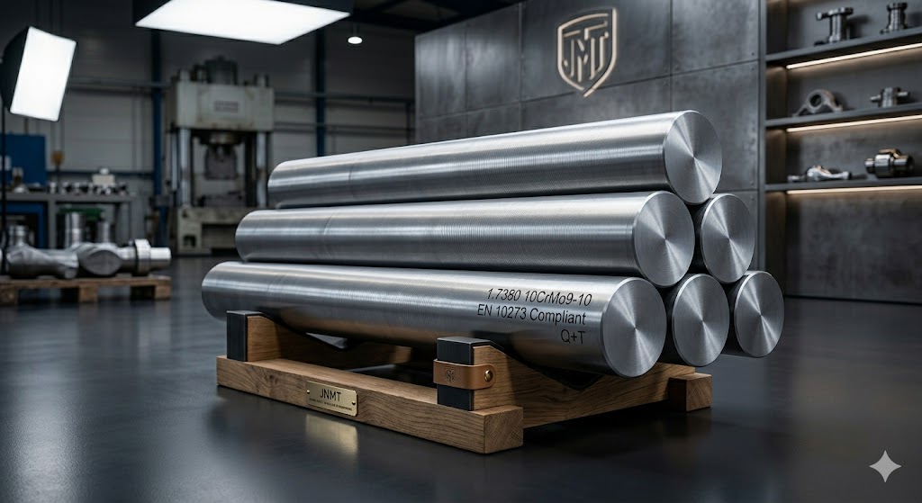
1.7380 Forged Bars
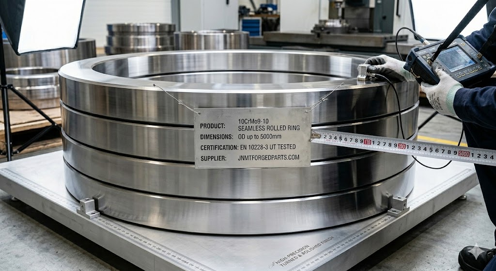
10CrMo9-10 Rolled Rings
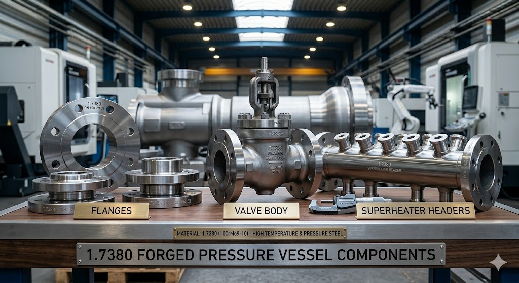
1.7380 Pressure Components
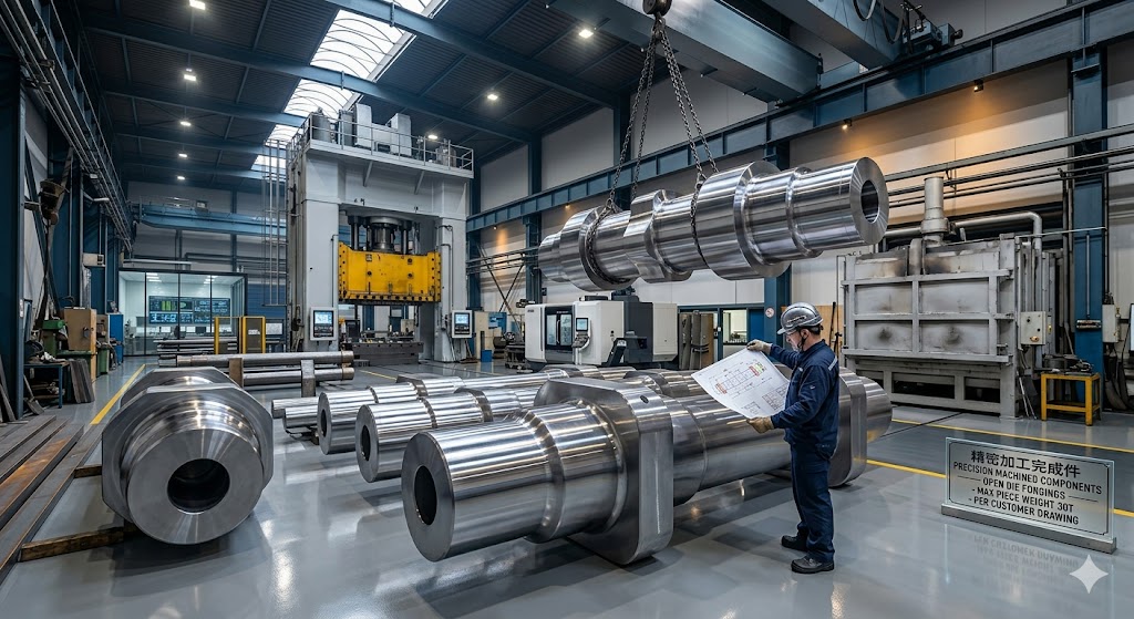
10CrMo9-10 Custom Forgings
Why Choose Our 1.7380 (10CrMo9-10) Forgings
25+ years forging experience, ISO 9001:2015 certified quality management system. Products manufactured to EN, DIN, ASTM and API material standards. EN 10204 3.1 MTC standard; 3.2 MTC with third-party witnessing available
Single piece weight from 30KGS to 30,000KGS, custom shapes and sizes per your drawings and technical requirements
100% NDT per EN 10228-3, minimum forging ratio ≥4:1 enforced on every heat, full material traceability from ingot to finished part
80,000㎡ factory with 10,000-ton hydraulic press, 5-axis CNC machining, fully automatic atmosphere-controlled heat treatment furnaces
EN 10204 3.1 MTC (standard) or 3.2 MTC with third-party witnessing (BV/SGS/TUV, arranged on request), full NDT reports, PMI verification, dimensional inspection report
Exported to 50+ countries including Germany, UK, Saudi Arabia, UAE, Australia, Netherlands — 200+ global power and petrochemical clients served
Get Custom Solution for Your 1.7380 Forging Project
Send your drawings and technical requirements — we respond with a professional quote within 24 hours
1.7380 (10CrMo9-10) Steel: Material Science & Why It Works at High Temperature
What is 1.7380 (10CrMo9-10) Steel?
1.7380, designated 10CrMo9-10 under the European EN system and equivalent to ASTM A335 Grade P22 in the United States, is a low-alloy chromium-molybdenum pearlitic steel specifically engineered for continuous high-temperature and high-pressure service. The designation encodes its composition: the "10" denotes approximately 0.10% carbon, "Cr9" refers to the 2.0–2.5% chromium content (expressed as 9× the percentage for two-digit alloy steels in EN nomenclature), and "Mo10" indicates 0.9–1.1% molybdenum.
The alloy occupies a critical design space in the global high-temperature steel hierarchy — significantly more capable than carbon steels and low-chromium grades like 16Mo3 (1.5415), yet far more weldable and economical than the advanced 9–12% chromium martensitic steels such as P91 or P92. This balance has made it the workhorse material for power plant boilers, petrochemical reactors and oil & gas pressure components operating between 400℃ and 580℃ for over six decades.
The Metallurgical Science Behind 1.7380's High-Temperature Strength
Understanding why 10CrMo9-10 performs so well at elevated temperatures is essential for engineers specifying this material and for procurement teams evaluating whether a forging supplier truly understands what they are producing.
Chromium's role — carbide stability and oxidation resistance: The 2.0–2.5% chromium content in 1.7380 serves two critical functions simultaneously. First, chromium combines with carbon to form thermally stable alloy carbides (primarily M₇C₃ and M₂₃C₆ types). Unlike the iron carbide (Fe₃C, cementite) found in plain carbon steels, these chromium-rich carbides resist dissolution and coarsening at operating temperatures up to 580℃, preserving fine dispersion strengthening and blocking dislocation movement — the core mechanism of creep resistance. Second, chromium forms a thin, adherent Cr₂O₃-rich oxide layer on the steel surface, providing oxidation protection that extends service life without the need for coatings in most boiler and reactor environments.
Molybdenum's role — solid-solution strengthening and creep resistance: The 0.9–1.1% molybdenum is arguably the most important element in the alloy for long-term creep resistance. Molybdenum atoms, being significantly larger than iron atoms, cause substantial lattice strain in the ferritic matrix. This solid-solution strengthening effect is highly temperature-resistant and does not diminish with normal service ageing at 500–580℃. Additionally, molybdenum retards the coarsening of carbides during long-term service, maintaining the fine dispersion that anchors dislocations during creep. Field data from European thermal power plants confirm that 2.25Cr-1Mo forgings (1.7380) in steam headers retain creep rupture strengths close to their original design values after 100,000+ service hours at 550℃.
Why 580℃ is the practical service limit: Above approximately 580–590℃, two degradation mechanisms accelerate sharply. First, carbide dissolution rates increase dramatically, reducing the dispersion strengthening effect. Second, at these temperatures in certain service environments, sigma-phase (FeCr intermetallic) can begin to precipitate along grain boundaries over very long exposures, causing severe embrittlement. For these reasons, EN standards and ASME code cases define 580℃ as the upper service limit for 10CrMo9-10 in long-term pressure equipment design.
The pearlitic microstructure advantage for welding: Unlike the martensitic 9Cr steels (P91, P92) which require stringent preheat and precisely controlled post-weld heat treatment to restore toughness after martensite formation, 1.7380 transforms to a fine pearlite + bainite structure during normalization and tempering. This pearlitic microstructure is inherently less sensitive to hydrogen-induced cracking during welding, allows more forgiving preheat requirements (150–250℃ vs. 200–300℃ for P91), and accommodates minor PWHT temperature variations without the risk of re-austenitizing martensite. This metallurgical characteristic translates directly to lower fabrication risk and lower total cost for field-welded assemblies.
Key Performance Advantages in Forged Form
- Superior creep resistance vs. plain carbon steels: At 550℃, the 100,000-hour creep rupture strength of 1.7380 (approximately 60 MPa) is 5–6× higher than Grade P1 (0.5Mo) and 3× higher than Grade P11 (1.25Cr-0.5Mo), enabling longer intervals between maintenance shutdowns
- High-temperature oxidation resistance up to 580℃: The Cr₂O₃ passive layer limits scale growth to less than 0.2mm after 50,000 hours at 550℃ in steam — sufficient for most power plant and reactor design margins
- Excellent weldability with manageable PWHT: Carbon equivalent (CEV) typically in the range 0.60–0.75, requiring preheating of 150–250℃; PWHT at 720–750℃ restores full toughness and stress-relief without complex post-heating hold sequences
- Outstanding hardenability in large cross-sections: The Cr+Mo combination ensures through-hardening in quench-and-temper treatment even in sections exceeding 500mm diameter — critical for large forged valve bodies, reactor shells and turbine shafts where centerline properties are as important as surface properties
- Proven long-term hydrogen attack resistance: The Nelson Curve for 2.25Cr-1Mo steel demonstrates resistance to hydrogen attack at partial pressures up to 10 MPa and temperatures up to 450℃, making it suitable for hydrocracking reactors and hydrotreating service
- Excellent machinability in the normalized & tempered condition: Hardness range of 140–180 HB allows efficient CNC machining with standard tooling, reducing finished component lead times and costs
1.7380 (10CrMo9-10) International Equivalents — Full Cross-Reference Guide
1.7380 / 10CrMo9-10 is one of the most globally harmonized engineering steels, with closely matching equivalents across all major industrial standards. However, there are important differences in heat treatment conditions, impact test requirements, and applicable product forms that procurement engineers must understand before substituting one designation for another.
| Country / Region | Standard | Designation | Applicable Product Forms | Key Differences vs. EN 10028-2 |
|---|---|---|---|---|
| Europe (EN) | EN 10028-2 | 10CrMo9-10 / 1.7380 | Flat products (plates, sheets) for pressure | Reference standard — all others compared to this |
| Europe (EN) | EN 10216-2 | 10CrMo9-10 / 1.7380 | Seamless steel tubes for pressure | Additional elongation requirement for tubes; wall thickness affects heat treatment |
| Europe (EN) | EN 10273 | 10CrMo9-10 / 1.7380 | Hot-rolled steel bars for pressure fasteners | Tighter surface condition requirements; mandatory impact testing at 20℃ |
| Europe (EN) | EN 10253-2 | 10CrMo9-10 | Butt-welding pipe fittings | Wall thickness and fitting geometry govern applicable properties |
| USA (ASTM) | ASTM A335 | Grade P22 | Seamless ferritic alloy-steel pipe | Slightly broader C range (0.05–0.15%); no mandatory impact testing unless specified |
| USA (ASTM) | ASTM A182 | Grade F22 | Forged fittings and flanges | Higher minimum tensile (415 MPa); F22 Cl. 1 is annealed only, Cl. 3 is Q+T |
| USA (ASTM) | ASTM A336 | Grade F22 | Steel forgings for pressure and high-temperature parts | Additional ultrasonic testing requirements per ASTM A388 |
| Japan (JIS) | JIS G3462 | STBA24 | Alloy steel tubes for boilers and heat exchangers | Slightly different Si range (0.10–0.50%); JIS UT requirements per JIS G0587 |
| UK (BS) | BS 3059 Part 2 | Grade 622 | Steel boiler and superheater tubes | Largely superseded by EN 10216-2; some legacy UK power plants still specify BS 622 |
| France (NF) | NF A36-209 | 10CD9.10 | Plates and sections for pressure vessels | Largely superseded by EN 10028-2 post EU harmonization |
| China (GB) | GB/T 5310 | 12Cr2Mo1 | Seamless steel tubes for high-pressure boilers | Slightly higher minimum Cr (2.0–2.5%) and broader Mo (0.9–1.1%); in practice identical alloy chemistry |
| Russia (GOST) | GOST 20072 | 15KhM | Heat-resistant steel for tubes and fittings | Different alloy — 15KhM is 1Cr-0.5Mo grade, NOT equivalent; use 10KhMFT or X10CrMoVNb for closer match |
⚠ Critical Note for Procurement Engineers
ASTM A182 Grade F22 Class 1 (annealed condition) is NOT equivalent to EN 10028-2 10CrMo9-10 in the Q+T condition. Class 1 has a minimum yield strength of only 205 MPa vs. 310 MPa for the EN Q+T grade. Always specify F22 Class 3 (Q+T) when replacing EN 10CrMo9-10 in PED-regulated applications. Similarly, the Russian 15KhM is a 1Cr-0.5Mo grade — confirm alloy chemistry before accepting it as a substitute for 1.7380 in high-temperature service above 520℃.
1.7380 vs. Alternative High-Temperature Steels — Engineer's Selection Guide
Selecting the correct chrome-molybdenum steel grade is one of the most consequential material decisions in high-temperature pressure equipment design. Choosing the wrong grade can result in either overdesign and unnecessary cost, or unsafe service conditions. Based on 25+ years of producing forgings for global clients, our technical team has compiled the following practical selection matrix.
| Property / Criterion | 16Mo3 (1.5415) 0.5Mo Steel | 13CrMo4-5 (1.7335) 1.25Cr-0.5Mo | 10CrMo9-10 (1.7380) 2.25Cr-1Mo | X10CrMoVNb9-1 (1.4903) P91 / 9Cr-1Mo-V |
|---|---|---|---|---|
| Max Continuous Service Temp. | 530℃ | 560℃ | 580℃ | 620℃ |
| Min. Yield Strength (RT, Q+T) | 275 MPa | 290 MPa | 310 MPa | 415 MPa |
| Creep Rupture Strength at 550℃, 10⁵h | ~15 MPa | ~40 MPa | ~60 MPa | ~100 MPa |
| Weldability (preheat & PWHT complexity) | Very Good (100–150℃ preheat) | Good (150–200℃ preheat) | Good (150–250℃ preheat) | Moderate (200–300℃, strict PWHT) |
| Oxidation Resistance | Moderate | Moderate | Good | Excellent |
| Hydrogen Attack Resistance (Nelson Curve) | Limited (below 400℃) | Moderate | Good (to 450℃/10MPa) | Excellent |
| Large Forging Machinability | Excellent | Very Good | Very Good | Moderate (harder) |
| Material Cost (relative) | Low | Moderate | Moderate | High |
| PWHT Sensitivity Risk | Very Low | Low | Low | High (re-hardening risk) |
| Typical Applications | Low-pressure steam up to 500℃ | Boiler tubes, steam headers to 560℃ | Supercritical boilers, reactors, wellheads 400–580℃ | Ultra-supercritical boilers, highest-temp steam lines 580–620℃ |
When to Specify 1.7380 Instead of P91
Many engineers default to P91 (X10CrMoVNb9-1) because of its higher strength numbers, but in applications where the operating temperature is below 580℃, 1.7380 is frequently the superior engineering choice for three reasons. First, P91 requires stringent PWHT control — the tempering window is narrow (750–780℃) and deviation by even ±15℃ can leave the weld heat-affected zone under-tempered, creating embrittlement risk in service. Second, Type IV cracking at the outer edge of the HAZ is a well-documented failure mode in P91 welded joints under creep conditions, a failure mode absent in 1.7380 pearlitic steels. Third, P91 requires 100% PWHT after any welding, including repair welds, while 1.7380 permits more flexible repair procedures. In our experience supplying forgings for German and UK power plants, procurement engineers transitioning from supercritical to advanced ultra-supercritical service often specify 1.7380 for auxiliary steam piping and headers even on P91 main steam projects, precisely to avoid the PWHT complexity.
When to Step Up from 13CrMo4-5 to 1.7380
13CrMo4-5 (1.7335, equivalent to ASTM A335 P11) is a reasonable choice for service up to about 540–550℃. When design temperature exceeds 545℃, or when the component operates continuously at high stress levels (> 100 MPa), or when hydrogen partial pressure exceeds approximately 4 MPa at 400℃, the additional Cr and Mo content of 1.7380 becomes technically necessary rather than merely desirable. We frequently assist clients in upgrading existing 1.7335 designs to 1.7380 when plant operating conditions are revised upward after initial commissioning.
Why Forged 1.7380 Outperforms Cast 10CrMo9-10 in High-Temperature Service
When engineers evaluate 10CrMo9-10 components, they sometimes ask whether casting can deliver equivalent performance to forging at lower cost. For ambient-temperature structural applications in low-stress environments, casting may be acceptable. For high-temperature pressure equipment subject to sustained stress, thermal cycling and creep, the gap in performance is significant and the choice of forging is not merely a preference but a structural engineering requirement.
In open die forging, mechanical working aligns the dendritic grain structure with the principal stress direction of the component. A forged flange ring, for example, has grain flow tangential to the bore, providing maximum hoop strength exactly where internal pressure demands it. Cast structures have random grain orientation with no such directional advantage.
Solidification shrinkage and dissolved gas evolution during casting create micro-voids and porosity that cannot be fully eliminated by HIP or heat treatment alone. These defects act as stress concentration sites that dramatically reduce fatigue life and fracture toughness in cyclic thermal service. Forging at a minimum ratio of 4:1 physically closes and welds these voids shut.
Comparative creep testing of wrought vs. cast 2.25Cr-1Mo specimens consistently shows 20–40% higher creep rupture lives in wrought forgings at equivalent stress and temperature. The refined grain structure, uniform carbide distribution, and absence of casting segregation all contribute to this advantage — critical in components designed for 100,000+ hour service lives.
High-temperature pressure vessels also undergo cold startups and pressure testing at ambient temperature. Forged 1.7380 in Q+T condition reliably achieves Charpy impact values of 55J longitudinal at 20℃ — sufficient to satisfy ASME and EN toughness requirements for pressure vessels down to 0℃ design temperature. Cast equivalents typically show 30–40% lower impact values with substantially higher scatter.
The uniform, fine-grained structure of properly forged 1.7380 provides excellent acoustic transmission for ultrasonic testing, allowing reliable detection of discontinuities as small as Ø2mm FBH (flat-bottom hole) equivalent per EN 10228-3 Class S3. Cast materials with variable grain size and inherent porosity create acoustic scattering that masks real defects and complicates UT interpretation.
Every forging we produce is directly traceable to a specific heat number at a specific steel mill. This enables full PMI verification and heat-by-heat chemistry documentation — requirements that are increasingly mandated by European PED notified bodies and that simply cannot be provided with the same certainty for welded or cast assemblies.
Custom 1.7380 (10CrMo9-10) Forged Products We Supply
We produce a comprehensive range of custom 10CrMo9-10 forged components, with single piece weight from 30KGS to 30,000KGS. Every product is manufactured to your drawing, heat treated to EN or ASTM requirements, and fully tested before shipment:
Round bars Ø50–1200mm, square bars, flat bars, rectangular bars and custom profiles. Length up to 12m. Available in normalized + tempered, annealed, or Q+T condition per EN 10273
Flange rings, turbine rings, seal rings, bearing rings. OD 200–5000mm, height up to 1500mm, wall thickness down to 50mm. Grain flow tangential. Per EN 10228-3 UT class S3/E3
Hubs, shells, cylinders, liners, hollow shafts. ID/OD ratio up to 1:3. Used for boiler drums, heat exchanger shells, pressure vessel cylinder sections
Forged discs up to Ø3500mm, blocks up to 5 tons, step and upset forgings. Used for pump casings, BOP components, reactor nozzles, turbine spacers
Valve bodies, bonnets, stems, gate/globe/check valve bodies, pump casings, impellers. CNC machined to your drawing, pressure tested, full PMI verification
Weld neck, slip-on, blind, socket weld flanges per ASME B16.5/B16.47 or EN 1092. Elbows, tees, reducers, caps. Rating up to ASME Class 2500 / PN 420
Forging Size & Tolerance Capabilities
| Product Form | Size Range | Weight Range | Standard Tolerance | Machined Tolerance |
|---|---|---|---|---|
| Round Bar | Ø50 – Ø1200mm | 30kg – 12,000kg | +4mm / -0mm OD | ±0.05mm OD |
| Seamless Rolled Ring | OD 200 – 5000mm | 50kg – 8,000kg | +8mm / -0mm OD | ±0.02mm bore |
| Hollow Forging / Sleeve | OD 200 – 1500mm | 100kg – 15,000kg | +6mm / -0mm | ±0.05mm |
| Disc / Block | Ø100 – Ø3500mm | 30kg – 20,000kg | +10mm / -0mm | ±0.05mm flatness |
| Valve Body / Complex Shape | Custom | 30kg – 5,000kg | Per drawing + 5mm machining stock | ±0.02mm critical dims |
| Large Custom Forging | Up to 4m length | Up to 30,000kg | Per customer drawing | ±0.1mm overall |
View our full product catalog: All Forged Products | All Alloy Steel Materials
Can't find the product form you need? Send your drawing — we will evaluate and provide a custom forging solution with accurate lead time and pricing
Get Free Custom Quote1.7380 (10CrMo9-10) Compliance Standards & Chemical Composition
Global Compliance Standards We Certify To
- EN 10028-2: Flat products for pressure purposes — defines chemistry, mechanical properties and test requirements for plate and sheet; our forgings are certified equivalent per mutual recognition with EN 10250-2
- EN 10216-2: Seamless steel tubes for pressure purposes — applicable for hollow forgings and forged tube blanks
- EN 10253-2: Butt-welding pipe fittings for high-temperature pressure service
- EN 10273: Hot rolled steel bars for pressure purposes — directly applicable to all our bar forgings and machined blanks
- EN 10228-3: NDT of steel forgings, Part 3 — UT for ferritic/martensitic forgings; we certify to quality class S3/E3 as standard, S2/E2 or S1/E1 on request
- PED 2014/68/EU (EU Pressure Equipment Directive): Our products are manufactured to the EN harmonized standards (EN 10028-2, EN 10273, EN 10228-3) that underpin PED compliance. EN 10204 3.2 MTC with third-party inspection body witnessing is available to support your EU-side PED conformity assessment process. Note: PED conformity assessment and CE marking are conducted by the EU importer/manufacturer of the finished pressure equipment, not by the raw material forging supplier
- API 6A (Wellhead and Christmas Tree Equipment): Products can be manufactured to meet API 6A material chemistry, mechanical property and dimensional requirements. We can provide full material test documentation consistent with API 6A material qualification. Note: API Monogram licensing is held by the finished equipment manufacturer; we supply API 6A-compatible forgings as a material subcontractor
- ASME Section VIII Div. 1 / Div. 2: For US-market pressure vessels and heat exchangers, we certify to ASME Code with A182 F22 Cl. 3 or A336 F22 chemistry and mechanical requirements
- DIN 17175: Legacy standard for seamless steel tubes at elevated temperatures — still specified by some retrofit and legacy power plant projects
- NACE MR0175 / ISO 15156: Sulphide stress cracking resistance material specification for sour oil & gas service — our 1.7380 forgings can be heat treated and documented to meet NACE MR0175 hardness and material requirements. NACE MR0175 is a material specification, not a company certification; compliance is demonstrated through hardness test results documented in the MTC
Chemical Composition — EN 10028-2 Smelt Analysis
| Element | Symbol | EN 10028-2 Limit (Mass %) | ASTM A335 P22 Limit | Metallurgical Role |
|---|---|---|---|---|
| Carbon | C | 0.08 – 0.14 | 0.05 – 0.15 | Carbide formation, base strength; controlled low to preserve weldability |
| Silicon | Si | Max 0.50 | Max 0.50 | Deoxidation, minor solid-solution hardening; kept low to avoid embrittlement |
| Manganese | Mn | 0.40 – 0.80 | 0.30 – 0.60 | Deoxidation, hardenability; wider range in EN vs. ASTM |
| Phosphorus | P | Max 0.020 | Max 0.025 | Harmful impurity — grain boundary embrittlement; stricter in EN |
| Sulfur | S | Max 0.010 | Max 0.025 | Harmful impurity — MnS inclusions reduce impact toughness and HIC resistance; significantly stricter in EN |
| Chromium | Cr | 2.00 – 2.50 | 1.90 – 2.60 | Stable carbide formation, oxidation resistance, hardenability — core alloying element |
| Molybdenum | Mo | 0.90 – 1.10 | 0.87 – 1.13 | Solid-solution strengthening, creep resistance, carbide coarsening retardation — most critical element for high-temperature performance |
| Nitrogen | N | Max 0.012 | — | Controlled to prevent strain ageing embrittlement; EN-specific requirement |
| Copper | Cu | Max 0.30 | — | Residual element limit; excess Cu can cause hot shortness during forging |
| Nickel | Ni | Max 0.30 | — | Residual element limit; beneficial for toughness in small amounts |
💡 Manufacturer's Note: Why Our S Content Is Often Below EN Limit
The EN 10028-2 maximum sulfur limit of 0.010% is already significantly stricter than the ASTM P22 limit of 0.025%. In our standard practice, we source ingots with sulfur controlled below 0.006% — well within the EN limit. This is not a marketing claim but a technical requirement driven by our experience with large forgings (above 5 tons): higher sulfur content promotes elongated MnS stringer inclusions that are revealed during UT inspection and require rejection. By controlling sulfur rigorously in the melt, we eliminate this rejection risk entirely and consistently achieve UT quality class S3/E3 without difficulty on forgings up to 30 tons.
Heat Treatment & Mechanical Properties — Complete Technical Data
Standard Heat Treatment Process
- Normalizing: Austenitizing at 930–960℃, air cooling — used for stress relieving rough forgings before final heat treatment; produces a fine pearlite-bainite microstructure with moderate strength
- Full Annealing: Austenitizing at 870–900℃, slow furnace cooling at ≤ 50℃/hour to below 600℃ — produces maximum softness for machining; not suitable for final delivery condition in most pressure equipment applications
- Isothermal Annealing: Austenitize at 860–890℃, cool to 680–720℃ and hold 4–8 hours, air cool — more uniform softness than full annealing, preferred for large sections where furnace cooling rate is difficult to control
- Quenching + Tempering (Q+T) — Recommended for all pressure equipment: Austenitize at 920–950℃, oil quench; temper at 730–760℃ with minimum hold time = (wall thickness in mm) ÷ 25 hours, minimum 1 hour, then air cool. Achieves the optimal combination of strength, toughness and creep resistance specified in EN 10028-2
- Post-Weld Heat Treatment (PWHT): 720–750℃, minimum hold time 2 minutes per mm of weld throat thickness, minimum 30 minutes total. PWHT is mandatory for 1.7380 welded assemblies operating above 300℃ or with wall thickness exceeding 12mm
💡 Why Our Furnace Records Matter for Your Creep Performance
The tempering temperature for 10CrMo9-10 is critical to final creep resistance. Undertempering (below 720℃) leaves excess martensite in the microstructure, elevating hardness but reducing creep life. Overtempering (above 780℃) risks partial austenitization and property loss. Our fully automatic heat treatment furnaces monitor temperature at 6 independent zones with ±5℃ accuracy, and every batch is archived with a full time-temperature curve. We provide this curve as part of the standard documentation package — not as an option. European notified bodies and DNV auditors consistently cite this as a strength of our quality system.
Room Temperature Mechanical Properties (Wall Thickness ≤ 60mm, Q+T Condition)
| Property | Symbol | EN Min. Requirement | Typical Achieved Value | Engineering Significance |
|---|---|---|---|---|
| Tensile Strength | Rm | 480 – 630 MPa | 545 – 580 MPa | Overall load-bearing capacity; kept in lower half of range by Q+T to optimize toughness |
| Yield Strength (Upper) | ReH | ≥ 310 MPa | 355 – 390 MPa | Determines design pressure rating per EN 13480 and ASME Section VIII |
| 0.2% Proof Strength | Rp0.2 | ≥ 280 MPa | 310 – 340 MPa | Used for design when ReH is not clearly defined; important for ASME code compliance |
| Elongation After Fracture | A5 | ≥ 20% | 23 – 28% | Ductility reserve for over-pressure events and proof testing; higher is better for safety |
| Reduction of Area | Z | ≥ 60% | 65 – 72% | Through-thickness ductility; indicates absence of internal defects and segregation |
| Charpy Impact (Longitudinal, 20℃) | KV2 | ≥ 40 J | 55 – 70 J | Fracture toughness for cold startup and brittle fracture prevention |
| Charpy Impact (Transverse, 20℃) | KV2 | ≥ 27 J | 35 – 48 J | Worst-case toughness direction; determines cold temperature operational limit |
| Brinell Hardness | HBW | 140 – 180 HBW | 152 – 170 HBW | Verifies correct tempering; hardness above 220 HBW indicates undertempering and potential hydrogen sensitivity |
Thickness Effect on Mechanical Properties
| Wall Thickness Range | Min. Yield Strength (ReH) | Min. Tensile Strength (Rm) | Note for Large Forgings |
|---|---|---|---|
| ≤ 60mm | 310 MPa | 480 – 630 MPa | Standard Q+T properties |
| 60 – 100mm | 295 MPa | 480 – 630 MPa | Slight reduction due to quench rate effect at section center |
| 100 – 160mm | 280 MPa | 470 – 620 MPa | Test specimens taken at T/4 depth per EN 10028-2 |
| > 160mm | 265 MPa | 450 – 620 MPa | Requires Jominy hardenability assessment; our technical team advises on procurement specification |
High Temperature Proof Strength & Creep Rupture Data
| Temperature | 0.2% Proof Strength (Min) | Creep Strength (10⁵h Rupture) | Creep Strength (10⁵h, 1% Strain) |
|---|---|---|---|
| 350℃ | 240 MPa | — | — |
| 400℃ | 220 MPa | 180 MPa | 145 MPa |
| 450℃ | 200 MPa | 140 MPa | 110 MPa |
| 500℃ | 180 MPa | 100 MPa | 75 MPa |
| 550℃ | 160 MPa | 60 MPa | 42 MPa |
| 575℃ | 148 MPa | 48 MPa | 32 MPa |
| 580℃ | 140 MPa | 40 MPa | 26 MPa |
Welding Performance Guide — Practical Parameters
1.7380 (10CrMo9-10) has good weldability with proper process control. Below are the parameters our engineering team provides to welding engineers receiving our forgings:
- Recommended welding processes: SMAW (111), SAW (12), GTAW/TIG (141), GMAW/MIG (131/135), electroslag welding (72) for large-section joins
- Preheat temperature: 150–250℃ for wall thickness ≤ 25mm; 200–250℃ for 25–60mm; 250℃ minimum for sections > 60mm. Preheat must extend 75mm each side of the joint and be maintained throughout welding
- Interpass temperature: ≤ 300℃ maximum — exceeding this can cause austenite formation in the HAZ and introduce untempered martensite on subsequent cooling
- PWHT temperature: 720–750℃. This window is critical: below 720℃, residual stress relief is incomplete and carbide precipitation is insufficient; above 760℃, risk of partial re-austenitization with associated microstructural damage
- PWHT hold time: 2 min/mm of maximum weld throat thickness, minimum 30 minutes. For wall thicknesses above 100mm, calculate hold time with thermal gradient modelling to ensure center temperature reaches the target range
- Consumable selection: ER90S-B3 / ER90S-G (GTAW wire), E9015-B3 / E9018-B3 (SMAW electrode), EB3 submerged arc wire with compatible basic flux. Hydrogen-controlled (low-hydrogen) consumables are mandatory — E9015 is preferred over E9010 for hydrogen content control
- Post-heat before PWHT: Where PWHT is delayed (common in field erection), maintain 250℃ post-heat for 1 hour after welding completion to allow hydrogen to diffuse out before the joint cools — this prevents hydrogen-induced cold cracking in the HAZ
Procurement Engineer's Guide to Ordering 1.7380 (10CrMo9-10) Forgings
Based on our experience processing thousands of purchase orders from engineering procurement teams across Europe, the Middle East and North America, we have compiled the most common specification issues, documentation requirements, and practical guidance that saves time and prevents costly revisions during order processing.
What to Include in Your Technical Specification
A complete technical specification for 1.7380 forgings should include the following, in order of importance:
- Applicable standard and grade: State explicitly — e.g. "EN 10028-2 Grade 10CrMo9-10 (1.7380)" or "ASTM A182 Grade F22 Class 3." Do not simply write "2.25Cr-1Mo steel" without a standard reference, as this creates ambiguity around heat treatment condition and test requirements
- Delivery condition (heat treatment): "Q+T (quenched and tempered)" should be specified unless there is a specific reason to request annealed or normalized. Q+T is the right condition for all pressure equipment applications above 400 °C
- NDT requirements: State UT class per EN 10228-3 (S1/E1, S2/E2 or S3/E3). If not specified, we default to S3/E3, which is suitable for most applications. If MT or PT is required on machined surfaces, state this explicitly. If UT mapping with full scan coverage report is required, note this in the specification
- MTC type: Specify EN 10204 3.1 or 3.2. For PED-regulated applications, 3.2 (witnessed by independent inspection body) is mandatory and should be confirmed with your notified body before ordering
- Third-party inspection: Specify inspector (BV, SGS, TUV, Lloyds, DNV, RINA etc.) if required, and the inspection scope (material review, heat treatment witnessing, mechanical test witnessing, dimensional inspection, PMI, final acceptance)
- Dimensional tolerances: Specify machining allowances, surface finish (Ra or Rz), and critical tolerances for bores, ODs and faces. We recommend providing a full 2D engineering drawing with GD&T annotations rather than a text description
- Impact test requirements: State test temperature if different from standard 20℃, minimum energy (J) if different from EN minimum, number of specimens, and whether longitudinal, transverse or both are required
- Marking requirements: Specify how you require parts to be marked — heat number, material grade, heat treatment condition, part number, weight, and whether low-stress stamp, vibro-engraving or paint stencil is acceptable for your application
How to Read a 1.7380 Mill Test Certificate (MTC)
- Confirm the MTC type: look for "3.1" or "3.2" certification statement and the authorized inspector's signature/stamp
- Verify the heat number on the MTC matches the heat number stamped on the forging — this is your traceability link and must match exactly
- Check that all listed chemical elements fall within EN 10028-2 or your specified standard limits — pay particular attention to Cr (2.00–2.50%), Mo (0.90–1.10%), S (max 0.010%), P (max 0.020%)
- Verify that mechanical test results come from test coupons taken from the same heat and same heat treatment batch as the delivered parts — not from a generic "typical" value database
- Confirm that tensile, yield and impact results all exceed EN minimums including any thickness-related reductions
- Check that the NDT report references the specific forging serial numbers delivered, not just the heat number — one heat can produce forgings of varying quality if forging parameters deviated
- Confirm the heat treatment curve record is appended (for 3.2 MTC, this is usually mandatory) and that the tempering temperature fell within 730–760℃ for the entire hold period
- Verify the PMI report shows both Cr and Mo peaks within range — PMI alone does not replace full chemistry analysis but confirms you have a Cr-Mo steel, not a plain carbon substitute
Common Specification Mistakes That Cause Delays
- Specifying "2.25Cr-1Mo" without a standard — forces us to request clarification on heat treatment condition, test requirements and MTC type before we can quote
- Requesting "EN 10204 3.2 MTC" without naming the inspection body — we need the specific inspector to be confirmed and available before scheduling production
- Specifying impact testing at -20℃ without confirming the steel grade supports this — standard 1.7380 Q+T is not guaranteed to EN limits at -20℃; this requires supplementary agreement and additional sampling
- Requesting ASTM F22 chemistry but EN 10204 3.2 MTC — the certification chain and testing protocols differ; specify one complete standard system
- Omitting machining allowances from the drawing — we will apply standard stock allowances per our internal procedure, which may not match your machining centre's requirements
25-Year Manufacturer's Insights: How We Prevent the 5 Most Common 1.7380 Forging Defects
In over 25 years of producing 10CrMo9-10 forgings for global clients, our quality team has investigated and resolved hundreds of nonconformance reports from both internal inspection and client feedback. The following are the five most common defects that arise in 1.7380 forgings from inadequate production control — and the specific preventive measures we have built into our standard process to eliminate them.
Defect 1: Coarse-Grain Microstructure from Over-Temperature Soaking
When a 10CrMo9-10 ingot is soaked at forging temperature (typically 1200–1250℃) for too long before working — a common occurrence when forge shops use conservative schedules for large ingots — abnormal grain growth occurs in regions where the critical deformation has not yet occurred. The result is a mixed coarse/fine grain structure that dramatically reduces impact toughness and creates variable UT attenuation, making reliable flaw detection difficult. Grain size coarser than ASTM No. 5 (approximately 90μm) significantly reduces the 100,000-hour creep rupture strength.
Our Prevention: We calculate maximum soak time for every ingot diameter using a validated heat transfer model. Forge shop pyrometers are calibrated quarterly. Any ingot that cannot be fully worked within the specified time window is returned to the furnace for a controlled re-heat cycle — never held at temperature beyond the calculated limit.
Defect 2: Internal Hydrogen Flakes from Rapid Post-Forge Cooling
Hydrogen flaking is the single most dangerous defect in large chrome-molybdenum forgings and is entirely invisible during visual inspection. During steelmaking, hydrogen dissolves in the liquid steel and becomes supersaturated in the solid during cooling. If large forgings are cooled too rapidly after forging, hydrogen cannot diffuse to the surface fast enough, and the internal supersaturation drives crack formation along grain boundaries, creating internal cracks called "flakes" that range from hairline fractures to cracks several centimetres long. These cracks are invariably oriented perpendicular to the working direction and are detected by UT as laminar-type discontinuities.
Our Prevention: All forgings above 200mm cross-section undergo controlled slow cooling in insulated boxes or pit furnaces immediately after final forging operations. Cooling rate is controlled to ≤ 30℃/hour down to below 300℃, then air-cooled. Forgings above 500mm diameter receive a hydrogen diffusion anneal at 620–650℃ for 4–8 hours before any heat treatment or UT inspection. We conduct baseline UT on every forging before heat treatment to establish a reference map — any change after heat treatment triggers investigation.
Defect 3: Decarburization from Uncontrolled Heat Treatment Atmosphere
Decarburization — the loss of carbon from the surface layer due to oxidizing atmosphere during heat treatment — is a particular concern for 1.7380 because even a 0.5mm decarburized layer significantly reduces the surface fatigue strength, and decarburized surfaces show anomalously low hardness that may be misinterpreted as undertempering during HBW spot checks. In pressure equipment subjected to thermal fatigue (boiler components, for example), a decarburized surface layer acts as a crack initiation site under cyclic thermal stress.
Our Prevention: Our heat treatment furnaces are equipped with atmosphere control systems (nitrogen blanket) that maintain oxygen content below 0.5% during the critical austenizing phase. Metallographic examination of a test coupon cross-section for decarburization depth is included in our standard quality plan for wall thicknesses below 50mm, where the decarburized layer represents a higher proportion of the section. Maximum permissible decarburization depth is 0.5% of section thickness, per EN ISO 3887.
Defect 4: Segregation in Large-Section Forgings
Chemical segregation — the concentration of alloying elements (particularly Mo, Cr and C) at the solidification front during ingot casting — creates bands of differing composition through the cross-section. In 10CrMo9-10, this manifests as alternating Mo-rich and Mo-lean bands that are visible under metallographic examination. Mo-lean bands have reduced creep resistance and, under the same service conditions, will creep at a faster rate than the surrounding material. In a forging designed as a homogeneous section, localized accelerated creep leads to stress redistribution and, ultimately, early failure.
Our Prevention: We source ingots only from electric arc furnace (EAF) and ladle refining furnace (LRF) producers with vacuum degassing capability, which significantly reduces centre segregation. For forgings above 2 tons, we require the steel mill to provide segregation index data from their internal process controls. Additionally, our minimum forging ratio of 4:1 substantially homogenizes the as-cast composition through mechanical working. We inspect cross-section macrostructure by sulphur print or macro-etching on the first-off of each new heat for large forgings.
Defect 5: Inadequate Forging Ratio Leading to Residual As-Cast Structure
The minimum forging ratio of 4:1 (reduction in cross-sectional area from ingot to forged blank) is specified in EN standards for good metallurgical reasons — it is the minimum deformation required to fully destroy the dendritic, as-cast grain structure, close micro-porosity, and distribute inclusions uniformly. Forge shops under cost pressure sometimes reduce the ingot cross-section less than required to use a smaller, cheaper ingot. The result is a finished forging with partially intact dendritic structure in the centre, showing dramatically reduced transverse impact toughness and often failing UT inspection as a diffuse scatter pattern rather than discrete indications.
Our Prevention: Every job traveller for 1.7380 forgings includes a calculated forging ratio based on the ordered dimensions and the ingot cross-section. Our production engineers are required to certify compliance with ≥ 4:1 ratio before the job is released for heat treatment. For complex shapes where measuring area reduction is non-trivial (steps, flanges, etc.), we use the equivalent strain approach validated against our press capacity data. Forging ratio is documented in the internal quality record and is available for client review on request.
Full-Process Quality Control & Inspection
Our quality management system for 1.7380 (10CrMo9-10) forgings is built on a principle that has guided us since 1997: a defect caught internally is a learning opportunity; a defect delivered to a client is a failure of the entire system. Every stage of the process has defined hold points that require documented sign-off before work proceeds.
Manufacturing Process Flow with Quality Hold Points
Full Inspection Items We Provide
- Non-Destructive Testing (NDT): Ultrasonic Testing (UT) per EN 10228-3 class S3/E3, Magnetic Particle Testing (MT) per EN 10228-1, Penetrant Testing (PT) per EN 10228-2, Radiographic Testing (RT) per EN 10228-4 on specific geometries
- Mechanical Properties Testing: Tensile test (Rm, ReH, Rp0.2, A5), Charpy impact (20℃ standard, other temperatures on request), Brinell hardness (HBW), high temperature proof strength test (on request)
- Chemical Analysis: Optical emission spectrometry (OES) for all elements, carbon-sulfur combustion analysis, Positive Material Identification (PMI) by XRF on every individual forging piece
- Metallographic Inspection: Grain size rating per ASTM E112, inclusion rating per EN 10247 / ASTM E45, decarburization depth per EN ISO 3887, microstructure classification
- Dimensional Inspection: CMM three-coordinate measurement, bore roundness, OD concentricity, flatness, perpendicularity per GD&T as specified; full dimensional report provided
- Pressure Testing: Hydrostatic pressure test, air seat test and gas tightness test on closed-form components (valve bodies, pressure vessel sections) as required by design standard
- High Temperature Creep Test: Performed in our in-house elevated temperature testing laboratory; 10,000-hour extrapolation from 1,000-hour test data on request for critical applications
Need a Custom Inspection Plan for Your 1.7380 Forging Project?
Our technical team will review your application requirements and prepare a detailed Quality Control Plan (QCP) aligned with your end-user specification
Contact Technical Team10CrMo9-10 (1.7380) Forgings — Global Project Reference Cases
The following cases represent actual projects completed by our team. Technical parameters are provided as illustrative reference data for engineers evaluating our capabilities against their specific project requirements.
Case 1 | Power Generation | 660MW Supercritical Boiler Project, Germany
A major German utility commissioned a 660MW supercritical thermal power unit requiring custom 10CrMo9-10 forged components for the primary boiler steam circuit — specifically superheater outlet headers, main steam pipelines, mixing manifolds and main isolation valve bodies. The design operating condition was 550℃ / 25MPa. The client’s engineering specification was EN 10273, EN 10228-3 S2/E2 UT class, EN 10204 3.2 MTC with TÜV Süd witnessing and PED 2014/68/EU Category III certification.
Our Scope: Over 2,100 individual forged components, of which there are 84 forged superheater header cylinders (OD 620mm × wall 90mm × length 3.8m, weight 12.5 tons each), 340 pipeline flanges (DN500 PN400, weight 380–520kg each) and 18 valve body forgings (weight 2.8–4.2 tons each). Total forged weight some 1,650 tons delivered over 14 months.
Main Technical Challenges Overcome: The 12.5-ton header cylinders required a forging ratio of exactly 4.2:1 from a 180-ton ingot, validated by recorded press tonnage and dimensional measurements at each reduction step. UT inspection per EN 10228-3 S2/E2 on these hollow cylinders required full scan coverage including compound-angle probing of the bore-to-wall interface region — a technically demanding scan pattern that our UT team developed specifically for this project geometry. All 84 cylinders achieved clean acceptance.
Outcome: All components achieved EN 10204 3.2 MTC with TÜV Süd witnessing, on-time delivery of 97.6% (the remaining 2.4% were reshipped within 5 days of original target date). The boiler has operated at design conditions for over 6 years without a single reported material-related issue.
Case 2 | Nuclear Power | Generation III Reactor Coolant System, China
A Chinese nuclear power operator required 1.7380 forgings for the conventional island section of a Generation III pressurised water reactor — specifically main coolant pump casings (non-nuclear island boundary), impellers, shaft seal rings and auxiliary feedwater system valve bodies. Nuclear-grade material traceability requirements applied: every forging required heat-level documentation from iron ore to finished part, and all inspection records were subject to 40-year archival requirements.
Our Scope: 24 pump casing forgings (weight 3.2 tons each), 24 impeller forgings (weight 380–460kg), 96 seal ring forgings (weight 45–85kg), 48 valve body forgings (weight 150–420kg). Total: 192 forging pieces across 4 size categories, all requiring RT (radiographic testing) in addition to UT and MT, and low-temperature impact testing at -20℃.
Key Technical Challenges Overcome: The -20℃ impact requirement (minimum 40J longitudinal, 27J transverse) is significantly more demanding than the EN standard 20℃ test and required supplementary process optimization. We got this through tighter Mn content control (targeting 0.65–0.75% rather than the full 0.40–0.80% range) and by optimizing the tempering temperature to the upper end of the allowable range (755℃) to maximize low-temperature toughness without exceeding the 760℃ ceiling. Average achieved -20℃ longitudinal impact: 52J.
Outcome: 100% acceptance on all 192 pieces. Nuclear traceability documentation chain verified by the client's quality assurance team and the regulatory inspector. All products have been in safe service for over 5 years.
Case 3 | Oil & Gas | Sour Gas Field Wellhead Equipment, Saudi Arabia
A major EPC contractor working for a Saudi Arabian national oil company required 10CrMo9-10 forgings for wellhead Christmas tree assemblies, production manifold flanges and downhole safety valve bodies destined for a high-pressure, high-temperature sour gas field (H₂S partial pressure: 0.35MPa, CO₂ partial pressure: 0.8MPa, operating temperature: 120–490℃, surface wellhead pressure: 69 MPa / 10,000 PSI). The applicable standards were API 6A Product Specification Level (PSL) 3, NACE MR0175 / ISO 15156, and the client's supplementary requirements document.
Our Scope: 1,520 individual forged components including Christmas tree body forgings (API 6A 10,000 PSI × 3-1/16" through 7-1/16" bores), production manifold flanges, choke body forgings and tubing hanger forgings. NACE MR0175 compliance required final hardness below 22 HRC (237 HBW) across the entire cross-section — including after any required weld repair — and total dissolved hydrogen content below 2 ppm.
Key Technical Challenges Overcome: Achieving NACE hardness compliance uniformly across large choke body forgings (OD 380mm) required precise tempering temperature calibration. Here, the 6-zone monitoring of our atmosphere controlled furnace played a vital role. The temperature difference of ±5℃ across the furnace load led to a hardness difference of about ±6 HBW. This is well within the tolerance margin. All 1,520 pieces met NACE hardness requirements on first inspection, with no rejections.
Outcome: Full API 6A PR2 pressure testing completed with zero test failures. BV third-party inspection witnessed all mechanical tests and dimension tests. Delivered to Saudi Arabia port in 5 container shipments, all within the contracted 35-day lead time window.
Case 4 | Petrochemical | Hydrocracking Reactor Project, Thailand
A 10 million-ton/year integrated refining and petrochemical complex in Thailand required 1.7380 forged components for hydrocracking reactors and associated high-temperature, high-hydrogen-partial-pressure piping. Design conditions: 540℃, 18MPa, H₂ partial pressure 8.5MPa. Nelson Curve compliance for 2.25Cr-1Mo at these conditions requires demonstration that operating conditions fall within the established curve boundaries — which they did, with a design margin maintained above the API 941 curve.
Our Scope: 8 reactor shell ring forgings (OD 2800mm, wall thickness 280mm, height 600mm, weight 28 tons each), 320 reactor nozzle forgings (various sizes, DN80–DN400, pressure class 1500), 64 heat exchanger tube sheet forgings (Ø1200–2200mm, thickness 180–320mm). Total forged weight: approximately 380 tons.
Main Technical Challenges Overcome: The 28-ton reactor shell ring forgings represent some of the largest 1.7380 forgings we have ever produced. At 280mm wall thickness, achieving centre properties meeting EN 10028-2 requirements (particularly the 265 MPa minimum yield strength at this thickness class) required careful ingot chemistry targeting — specifically Mo at the upper end of the 0.90–1.10% range and Mn at 0.70–0.75% — combined with extended tempering cycles of 12 hours at 755℃ to guarantee full through-thickness tempering. All 8 ring forgings achieved EN 10204 3.2 MTC with Bureau Veritas witnessing.
Outcome: The hydrocracking unit achieved mechanical completion on schedule. Our forged components passed all post-installation pressure tests. After 4+ years of operation in H₂ service at 540℃, no defects or dimensional anomalies have been reported by the operator.
What Our Global Clients Say
"We have been cooperating with Jiangsu Liangyi for 4 years, supplying 1.7380 forged components for our German thermal power projects. What distinguishes them from other Chinese forging suppliers is the documentation quality — heat treatment curves, UT scan maps, and the completeness of the 3.2 MTC package are consistently at the level we see from European mills. All products are 100% NDT qualified, delivery performance is above 95% on-time."
"We ordered custom 10CrMo9-10 seamless rolled rings and Christmas tree body forgings for a sour gas field in the UAE. Jiangsu Liangyi's technical team understood immediately that NACE MR0175 hardness compliance was the critical control parameter and communicated a clear plan for how they would manage it. The products passed all API 6A and NACE tests first time, and the lead time was actually 8 days ahead of schedule. We will definitely use them on our next Gulf project."
Frequently Asked Questions — 1.7380 (10CrMo9-10) Forgings
Inquiry for Custom 1.7380 (10CrMo9-10) Forged Parts
Jiangsu Liangyi is your reliable China manufacturer for high-quality 1.7380 (10CrMo9-10) forgings. ISO 9001:2015 certified quality system. Custom drawings are welcome — we will provide a professional technical solution and competitive quote within 24 hours. Products manufactured to EN/DIN/ASTM/API material standards; EN 10204 3.1/3.2 MTC and third-party inspection all supported.
Official page: https://www.jnmtforgedparts.com/1.7380-10crmo9-10-forged-parts.html