Jiangsu Liangyi Co Limited is an ISO 9001:2015 certified manufacturer of AISI 8622H forging parts, SAE 8622H forged steel components, and custom alloy steel forgings. We have operated our own forging workshop in Jiangyin, Jiangsu Province, China for over 20 years — which means every piece of technical knowledge on this page comes from our production floor, not from a datasheet. We have machined shafts, rejected heats, reworked case depths, and argued with metallurgists about quench rates. That is the experience we bring to your project.
We serve 300+ clients across 50+ countries — including wind turbine gearbox OEMs in Europe, oil and gas equipment builders in the United States, mining equipment manufacturers in Australia, and industrial machinery groups in Southeast Asia. Whether your requirement is a single prototype shaft for validation testing or a high-volume production run of case-hardened gear rings, we handle the full sequence in-house: raw material procurement, open die forging or seamless ring rolling, heat treatment, CNC machining, NDT, and final inspection — all with factory-direct pricing and documented lead times.
This page goes beyond a standard product listing. We explain why AISI 8622H behaves the way it does in a forging context, what questions you should ask any supplier, and exactly how to specify your order to avoid costly surprises. If you are a procurement engineer comparing suppliers, or a design engineer specifying a material for the first time, we hope this page gives you something genuinely useful — regardless of whether you ultimately buy from us.
AISI 8622H Steel — Quick Reference
Our AISI 8622H Forged Steel Products
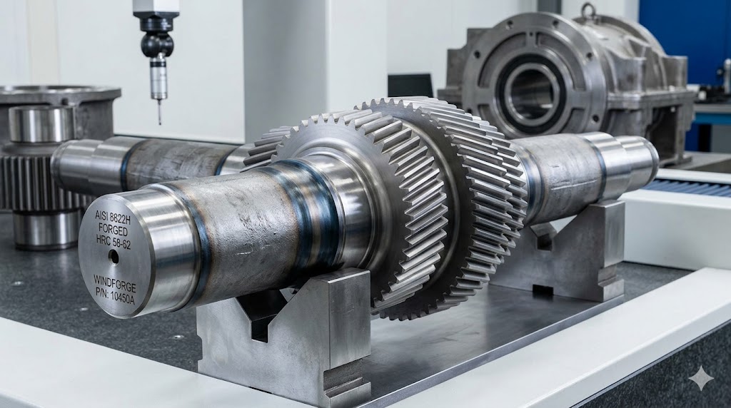
AISI 8622H Forged Gear Shafts
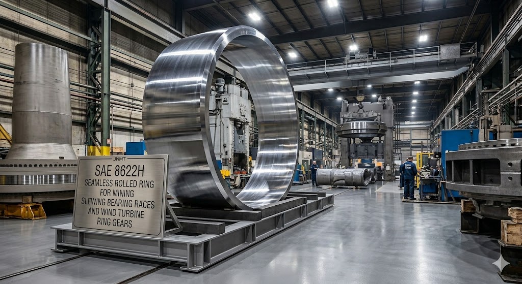
SAE 8622H Seamless Rolled Rings
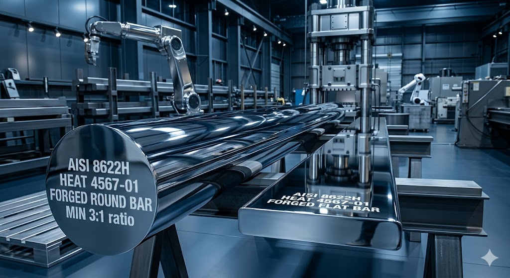
AISI 8622H Forged Bars & Blocks
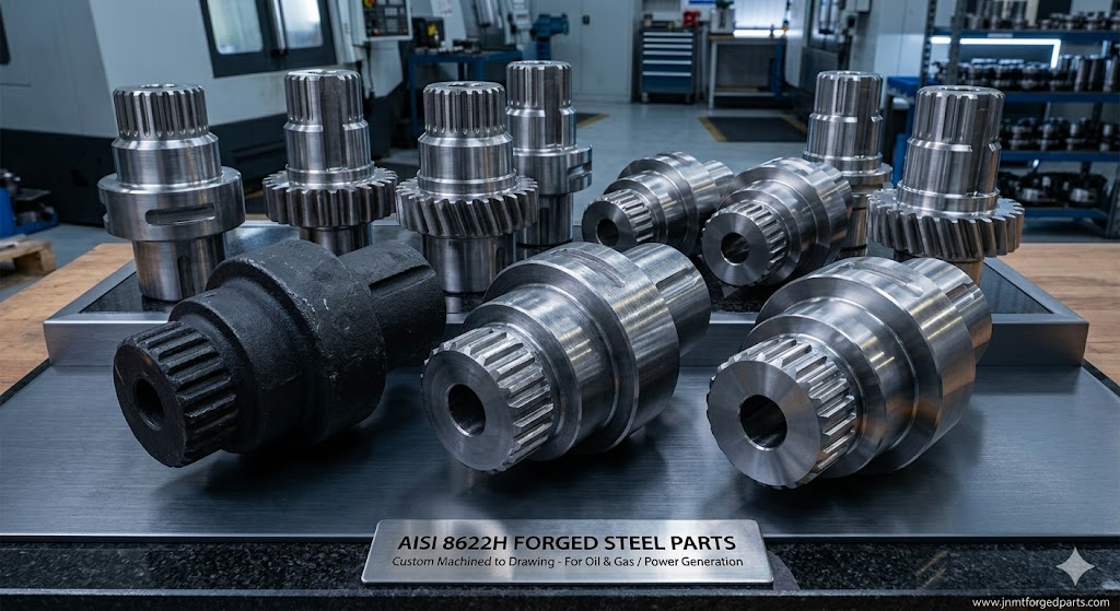
Custom 8622H Bespoke Forgings
Why the "H" in AISI 8622H Matters for Large Industrial Forgings
The letter "H" appended to a steel designation is not merely a marketing suffix — it is a contractual guarantee. When steel is ordered to the H-grade specification under ASTM A304, every heat of steel must produce a Jominy end-quench hardenability curve that stays within a defined minimum and maximum band. For AISI 8622H, that band is tighter than the standard AISI 8622 composition range allows.
Why does this matter in a forging context? Because a forging is rarely a small specimen. A gearbox input shaft for a 5 MW wind turbine may have a critical cross-section of 350–500 mm. A crusher eccentric shaft may be 600 mm in diameter and 2,500 mm long. At those dimensions, the hardenability of the steel — not just the surface — determines the core hardness and toughness that will carry the actual service loads. An ordinary AISI 8622 heat with hardenability at the low end of its composition range will produce a soft, low-strength core in a 400 mm section. A certified AISI 8622H heat, by contrast, guarantees that the core will achieve a minimum hardness at a defined depth, giving you the predictability that failure analysis engineers demand.
From Our Melting Records: In our experience, the lot-to-lot hardenability variation in standard AISI 8622 (non-H) steel can shift the J25 Jominy value by as much as 8–10 HRC between heats from the same mill, simply because the composition is allowed to vary across the full specified range. With 8622H, that variation is held to within ±3–4 HRC at the same position. For a procurement engineer, this means far more consistent post-heat-treatment inspection results and fewer costly non-conformances across production batches.
H-Grade vs. Standard Grade: The Practical Difference in a Forging Order
When you order AISI 8622H forgings from us, the H-grade requirement flows through our supply chain in three concrete ways:
- Raw material procurement: We order steel billets specifically certified to AISI 8622H with a mill-issued Jominy hardenability test report. We do not accept standard AISI 8622 billets on an 8622H order, even if the chemistry happens to fall within the H-grade window, unless it is accompanied by actual end-quench test data.
- Heat treatment process design: Because the hardenability band is guaranteed, our heat treatment engineers can design a carburizing + quenching cycle with confidence that the core will respond as calculated. This allows us to commit to specific core hardness targets on the inspection report — not just surface hardness.
- Inspection documentation: Every 8622H order ships with the full mill MTR showing the actual Jominy curve data, alongside our own heat treatment records and mechanical property certificates from test bars cut from the actual forging batch.
What Each Alloying Element in AISI 8622H Actually Does
Most supplier pages reproduce the composition table without explaining the metallurgical logic behind it. Understanding why each element is present — and what happens when it is at the high or low end of its specified range — helps engineers evaluate whether 8622H is the right grade for a specific application, and helps procurement teams ask the right questions during qualification.
Carbon content in the core is kept intentionally low (0.20–0.25%) to preserve core ductility and toughness after quenching. The surface carbon is built up to 0.7–0.9% during the carburizing step — this is where the high surface hardness originates. The low core carbon also means the core does not fully harden during quenching, producing the dual-property profile (hard case, tough core) that defines this grade.
Nickel is the primary toughness element in 8622H. It lowers the ductile-to-brittle transition temperature, which is why 8622H forgings perform reliably in cold-climate applications such as offshore wind turbines in the North Sea or mining equipment in northern Canada. Nickel also slightly improves hardenability and, critically, it promotes a finer martensite lath structure in the case — contributing to better fatigue resistance compared to Ni-free carburizing grades.
Chromium is the primary hardenability-enhancing element in this grade. It forms stable chromium carbides (Cr₇C₃, Cr₂₃C₆) in the case during carburizing, which improve wear resistance beyond what plain carbon martensite achieves. Chromium also retards grain growth during the carburizing cycle, keeping the austenite grain size finer and improving the toughness of the hardened case — a critical property for components subject to bending fatigue, such as gear teeth.
Molybdenum is arguably the most important element in 8622H for large-section forgings. It strongly improves hardenability with minimal increase in susceptibility to temper embrittlement. For large shafts that must be tempered slowly through the 350–550°C range, Mo suppresses the grain boundary segregation of phosphorus and tin that causes temper brittleness in Ni-Cr steels without Mo. Mo also refines carbide distribution in the case and contributes to hot hardness retention — useful in applications near elevated temperatures.
Manganese improves hardenability and deoxidizes the steel during melting (combining with sulfur to form MnS rather than FeS, which would cause hot shortness). In 8622H, Mn works in concert with Cr and Mo to provide the overall hardenability band defined by ASTM A304. The relatively tight Mn range (0.70–0.90%) versus standard AISI 8622 (0.70–0.90% nominally, but wider in practice) is part of what creates the tighter H-band.
Silicon is primarily a deoxidizer in 8622H, contributing to the killed steel designation that ensures no gas porosity in the solidified ingot. Silicon also strengthens the ferrite phase in the core and slightly raises the tempering resistance. It does not contribute directly to case hardenability. Keeping Si below 0.35% minimizes the risk of silicon oxides forming at the surface during carburizing, which can cause irregular carbon absorption — a practical processing concern for long carburizing cycles on large forgings.
Custom AISI 8622H Forging Shapes, Sizes & Manufacturing Limits
We manufacture the full range of industrial forging shapes in AISI 8622H. The table below summarizes our standard manufacturing limits — but these are not absolute ceilings. For components that push these boundaries, please contact our engineering team to discuss feasibility before submitting a drawing.
| Product Type | Typical Size Range | Max Weight / Dimension | Common Applications |
|---|---|---|---|
| Forged Round Bars & Rods | Ø 50 – Ø 800 mm | Up to 12,000 mm length | Shaft blanks, axle blanks, test material |
| Forged Shafts & Spindles | Ø 80 – Ø 1,200 mm | Up to 15,000 mm length; up to 30 tons | Gear shafts, rotor shafts, pinion shafts, drive shafts |
| Seamless Rolled Rings | OD 300 – OD 6,000 mm | Wall thickness from 50 mm; height up to 1,000 mm | Gear rings, bearing races, flange rings, slewing rings |
| Forged Discs & Hubs | Ø 200 – Ø 2,500 mm | Up to 8,000 mm height; up to 20 tons | Wheel blanks, turbine disc blanks, gear wheel blanks |
| Hollow Forgings (Tubes / Sleeves) | OD 150 – OD 1,200 mm, ID bore from 80 mm | Up to 8,000 mm length | Hollow shafts, cylinder bodies, valve bodies, sleeves |
| Forged Blocks & Plates | Up to 3,000 × 2,000 × 800 mm | Up to 50 tons | Die blocks, mold bases, structural plates |
| Step Shafts & Complex Profiles | Custom — per drawing | Per individual assessment | Crankshafts, eccentric shafts, compound gear shafts |
All products are available in the as-forged condition (normalized or annealed), rough-machined (allowing +3–10 mm finish allowance), or fully finish-machined to your drawing tolerances. We can hold dimensional tolerances to IT7 grade for most features on finish-machined components.
Have a drawing or specification for AISI 8622H forgings? Send it to us for a free technical review and quotation — we respond within 24 hours on business days.
Where Our AISI 8622H Steel Comes From — Melting Route & Cleanliness Control
One of the most important questions to ask any forging supplier is: "Where does your raw material come from, and what is the melting route?" The answer has a direct impact on the fatigue life and impact toughness of the finished forging — properties that do not show up in a standard chemical composition certificate.
All AISI 8622H steel we use is produced via a three-stage clean steel melting route:
Electric Arc Furnace (EAF) — Primary Melting
We specify EAF-melted steel rather than basic oxygen furnace (BOF) steel for AISI 8622H. EAF allows tighter control over charge composition and better flexibility for producing low-volume heats of specialty alloy grades. The chemistry is brought to the target range at this stage, with initial deslagging to remove phosphorus below 0.030%.
Ladle Refining Furnace (LF) — Composition & Inclusion Control
After EAF tapping, the heat is transferred to the ladle furnace for final chemistry trim, desulfurization (to ≤0.015% for critical orders), temperature homogenization, and reduction of oxidic inclusions through synthetic slag treatment. This stage is where the Mn, Ni, Cr, and Mo additions are fine-tuned to the H-grade hardenability target. LF treatment also produces a reducing slag environment that converts hard, angular alumina inclusions to softer, more deformable calcium aluminates — critical for improving fatigue properties in the final forging.
Vacuum Degassing (VD) — Hydrogen & Oxygen Removal
Vacuum degassing is non-negotiable for forgings with section sizes above 150 mm. Without it, dissolved hydrogen in the steel can cause hydrogen-induced flaking (white spots) during slow cooling of large ingots — a defect that is invisible on the surface but catastrophic in service. Our specification requires: hydrogen content ≤ 1.5 ppm (typically achieved ≤ 1.0 ppm), oxygen content ≤ 20 ppm, and nitrogen content ≤ 80 ppm after VD treatment. These values are documented in the mill's gas analysis certificate, which we include in the shipment documentation upon request.
Why This Matters to You: A forging produced from non-VD steel that is used in a large-section application (say, a 400 mm crusher shaft) carries a hidden risk of hydrogen flaking that may not be detected by standard surface NDT. We have encountered competitor products — specifically from suppliers who do not specify VD — that showed internal lamination defects on UT inspection after machining. Specifying "EAF + LF + VD" in your purchase order protects you from this risk. All our 8622H orders above 100 kg / 150 mm section size are automatically supplied from VD-treated heats.
Inclusion Rating Standards We Use
We assess non-metallic inclusion cleanliness per ASTM E45 Method A (worst-field rating) on representative samples from each heat. For standard industrial forgings, we target inclusion ratings of A ≤ 1.5, B ≤ 1.5, C ≤ 1.0, D ≤ 1.5. For critical applications (wind turbine main shafts, high-cycle fatigue components), we tighten this to A ≤ 1.0, B ≤ 1.0, C ≤ 0.5, D ≤ 1.0 — and this becomes a contractual inspection requirement.
Forging Ratio, Reduction, & Why It Affects Your Component's Performance
The forging process does not merely shape the steel into the desired geometry — it fundamentally transforms the internal microstructure in ways that cannot be replicated by simply machining a piece of rolled bar to the same dimensions. Understanding the concept of forging ratio helps engineers and procurement teams specify their requirements correctly and evaluate whether a supplier's process is adequate for the application.
What Is Forging Ratio and Why Does It Matter?
Forging ratio (also called reduction ratio or working ratio) is defined as the ratio of the initial cross-sectional area of the starting ingot or billet to the final cross-sectional area of the forged product. A forging ratio of 4:1 means the steel was reduced to one-quarter of its original cross-sectional area during forging. This mechanical working has three key effects:
- Closure of solidification porosity: All large ingots contain some degree of central porosity, pipe, or micro-shrinkage from the solidification process. Forging ratio of at least 2:1 is required to begin closing these defects; ratios of 3:1 or above are generally considered sufficient for full closure in most industrial applications.
- Grain refinement: Repeated deformation breaks up the original coarse-grained as-cast structure, replacing it with a finer, more uniform equiaxed grain structure. After subsequent normalizing heat treatment, a well-worked 8622H forging will typically exhibit an ASTM grain size of 5–8 (per ASTM E112), compared to grain size 1–3 in an as-cast ingot.
- Fiber flow alignment: Forging aligns the non-metallic inclusions and carbide bands along the forging direction, creating what metallurgists call "fibrous flow lines." When the forging is designed correctly, these flow lines run parallel to the primary stress direction in service — dramatically improving fatigue strength and impact resistance in the transverse direction versus machined bar.
| Application Criticality | Min. Forging Ratio | Typical Grain Size Achieved | Example Components |
|---|---|---|---|
| General industrial | 3:1 | ASTM 6–7 | General shafts, blocks, standard bars |
| Critical rotating or fatigue-loaded | 5:1 | ASTM 7–8 | Gear shafts, rotor shafts, gear rings |
| High-cycle fatigue (wind, aerospace) | 6:1 and above | ASTM 8+ | Wind turbine main shafts, aircraft landing gear forgings |
| Seamless rolled rings | Ring rolling provides equivalent of 4:1+ | ASTM 6–8 | Bearing races, slewing rings, gear rings |
For our standard AISI 8622H forged shaft and gear component orders, we target a minimum forging ratio of 5:1 from ingot to finished forging, and document the starting ingot weight versus finished forging weight in our internal process control records. We can provide this documentation upon request as part of the quality dossier for your project.
A Note on "Forged" vs. "Rolled" Bar: Some suppliers quote "forged bar" meaning hot-rolled bar produced on a bar mill — not open die forged from an ingot. Hot rolling does provide mechanical working, but the process route, forging ratio records, ingot size, and quality control documentation are fundamentally different. For critical applications requiring traceable forging ratio and ingot-specific material records, always specify "open die forged from killed steel ingot" and request the ingot weight and forging sequence documentation.
AISI 8622H Chemical Composition — ASTM A304 Reference Values
The following composition ranges are the reference values per ASTM A304 for the AISI 8622H H-grade designation. Note that the H-grade ranges are deliberately tighter than the standard AISI 8622 composition in ASTM A29, specifically to guarantee the hardenability band. Our incoming material inspection verifies conformance to these ranges using a direct-reading optical emission spectrometer (OES), with results documented on the material test report.
| Element | H-Grade Range (wt %) | Primary Function in 8622H |
|---|---|---|
| Carbon (C) | 0.20 – 0.25 | Controls core hardness; kept low to preserve toughness |
| Manganese (Mn) | 0.70 – 0.90 | Hardenability, deoxidation, prevents hot shortness |
| Nickel (Ni) | 0.40 – 0.70 | Core toughness, low-temperature impact resistance |
| Chromium (Cr) | 0.40 – 0.60 | Hardenability, carbide stability, wear resistance in case |
| Molybdenum (Mo) | 0.15 – 0.25 | Large-section hardenability, temper embrittlement resistance |
| Silicon (Si) | 0.15 – 0.35 | Deoxidation, ferrite strengthening |
| Sulfur (S) | ≤ 0.040 (critical orders: ≤ 0.015) | Controlled low; MnS inclusions detrimental to transverse toughness |
| Phosphorus (P) | ≤ 0.035 | Controlled low; grain boundary embrittlement risk |
| Iron (Fe) | Balance | — |
For critical fatigue applications, we recommend specifying an additional S ≤ 0.015% requirement in your purchase order. This tighter sulfur limit significantly reduces MnS inclusion stringer length and improves transverse Charpy impact values, typically by 20–40%. There is a modest material cost premium for this specification.
AISI 8622H Mechanical Properties — Typical Values & Section Size Effects
Published mechanical property values for any alloy steel are only meaningful if the test specimen size and location are clearly defined. A 25 mm round test bar cut from a small normalized specimen will produce very different results from a Ø 250 mm shaft section. This is called the "mass effect" or "section size effect" — and it is one of the most commonly overlooked details in steel forgings procurement.
Typical Mechanical Properties After Quenching & Tempering (Q&T)
| Property | Test Condition | Typical Value | Unit |
|---|---|---|---|
| Tensile Strength (Rm) | 25 mm round specimen, Q&T | 930 – 1,100 | MPa |
| 0.2% Proof Strength (Rp0.2) | 25 mm round specimen, Q&T | 780 – 950 | MPa |
| Elongation (A5) | 25 mm round specimen, Q&T | ≥ 12 | % |
| Reduction of Area (Z) | 25 mm round specimen, Q&T | ≥ 40 | % |
| Charpy Impact Energy (KV2, longitudinal) | Room temperature (20°C) | ≥ 55 | J |
| Charpy Impact Energy (KV2, transverse) | Room temperature (20°C) | ≥ 35 | J |
| Core Hardness (Q&T only) | 25 mm specimen | 28 – 38 | HRC |
| Surface Hardness (carburized + quenched + tempered) | Case ≥ 0.5 mm from surface | 58 – 62 | HRC |
| Core Hardness (carburized) | At geometric center | 30 – 45 | HRC |
| Effective Case Depth (550 HV limit) | Adjustable | 0.8 – 2.5 | mm |
| Brinell Hardness (annealed) | Annealed condition | 167 – 229 | HBW |
Section Size Effect — How Properties Degrade in Large Forgings
The following table illustrates how the through-hardening mechanical properties of AISI 8622H degrade as forging section size increases, due to reduced quench rates at the center. These values are based on our internal test records from production forgings tested at ¼-radius and centerline positions. Properties in the case-hardened zone are less affected by section size — but core toughness values drop significantly in large sections, which must be accounted for in fatigue and fracture mechanics calculations.
| Section Diameter | Test Position | Tensile Strength (MPa) | Yield Strength (MPa) | Elongation (%) | Core Hardness (HRC) |
|---|---|---|---|---|---|
| 25 mm (reference) | Center | 930 – 1,100 | 780 – 950 | ≥ 12 | 28 – 38 |
| 100 mm | ¼ radius | 880 – 1,050 | 740 – 900 | ≥ 11 | 25 – 35 |
| 200 mm | ¼ radius | 830 – 980 | 700 – 850 | ≥ 10 | 22 – 32 |
| 300 mm | ¼ radius | 780 – 920 | 650 – 800 | ≥ 10 | 20 – 30 |
| ≥ 400 mm | ¼ radius | Agree target values with supplier — section by section | — | — | 18 – 28 typical |
For forgings with ruling section above 200 mm, we strongly recommend agreeing specific minimum mechanical property targets in the purchase order, specifying both the test position (¼-radius or centerline) and the number of tests per order (per heat, per piece, or per batch). Test bars should ideally be taken from the actual forging — not from a separately heat-treated witness bar — for the most reliable results. We support either approach and will advise based on your budget and criticality level.
Our Standard Practice: For all AISI 8622H orders with a forging ruling section above 150 mm, we automatically attach test bars to the actual forgings during heat treatment. This means the test coupons experience identical thermal history to the component itself — the only way to truly verify that the properties in the report represent what is inside the finished piece.
Heat Treatment Process & Case Depth Engineering Guide
Heat treatment is where the potential of AISI 8622H is either realized or wasted. A suboptimal carburizing cycle — too short, too shallow, wrong carbon potential, wrong quench rate — will produce a component that looks correct on surface hardness testing but fails prematurely in service due to sub-surface fatigue crack initiation at the case-core transition.
Standard Case Carburizing Process Sequence
Post-Forge Normalizing at 920–940°C
Immediately after forging, the component is air-cooled from 920–940°C to refine the as-forged grain structure, relieve forging stresses, and produce a uniform ferrite-pearlite microstructure as the starting condition for subsequent machining and carburizing. Normalizing temperature is logged by our thermocouple recording system. For very large sections (≥ 500 mm), we may perform two normalizing cycles to ensure full transformation throughout the section.
Rough Machining to Near-Net Dimensions
Rough machining is performed after normalizing, leaving a 1.5–5 mm finish allowance depending on component size and distortion tolerance. This minimizes the total carbon-enriched layer that must be removed after carburizing while providing enough stock for straightening and finish grinding.
Case Carburizing at 920–930°C, Controlled Carbon Potential
Parts are loaded into our sealed-atmosphere carburizing furnace. Carbon potential is maintained at 0.75–0.85% using an endothermic gas carrier with enrichment gas (natural gas or propane). The cycle time is calculated from our empirical case depth charts to achieve the target effective case depth. We use a two-stage cycle: a high-carbon-potential boost phase (Cp 1.1–1.2%) followed by a diffusion phase (Cp 0.75–0.80%) to produce a smooth carbon gradient from surface to core and avoid excessive retained austenite at the surface.
Reheating to 840–860°C for Austenitization
After carburizing, parts are reheated to 840–860°C (below the carburizing temperature) to produce a finer, more homogeneous austenite grain before quenching. This reheat step — sometimes omitted by less careful heat treaters — is essential for achieving fine martensite lath size in the case and maximum case toughness.
Oil Quenching with Agitation Control
Parts are quenched in hot oil (60–80°C) with controlled agitation. Oil temperature and agitation speed are logged. For large or complex-geometry parts, we design custom quench fixtures to minimize distortion. Press quenching is available for thin gear rings and components with distortion tolerance ≤ 0.05 mm/100 mm.
Low-Temperature Tempering at 150–180°C
Parts are tempered within 4 hours of quenching to minimize quench crack risk. The low tempering temperature (150–180°C) relieves quench stresses and reduces retained austenite without significantly sacrificing surface hardness. Tempering is held for minimum 2 hours per 25 mm of section. Final surface hardness after tempering is verified by Rockwell C testing at multiple points per component.
Final Inspection, Straightening & Dispatch
After heat treatment, 100% of components are checked for dimensional distortion. Shafts with TIR bow above tolerance are cold straightened using a hydraulic press, followed by a stress-relief temper at 120°C. Final surface hardness, case depth (by Vickers hardness traverse on cross-section witness specimens), and dimensional check are recorded and included in the shipping inspection document.
How to Select the Right Case Depth for Your Application
Case depth is one of the most important specifications on an AISI 8622H forging drawing — and one that engineers most often simply leave to the supplier's judgment. That leads to components that are either under-depth (early fatigue failure from sub-surface spalling) or over-depth (brittle case that chips under impact). The following guide is based on our production experience across thousands of case-hardened forgings:
| Application Type | Effective Case Depth (ECD at 550 HV) | Engineering Basis |
|---|---|---|
| Lightly loaded gear teeth (module 2–5 mm) | 0.4 – 0.8 mm | ECD ≈ 0.1 × module is a widely used starting point |
| Medium-loaded gears (module 6–12 mm) | 0.8 – 1.5 mm | Hertzian contact stress drives sub-surface shear maximum depth |
| Heavy gears, wind turbine ring gears (module 12–25 mm) | 1.5 – 2.5 mm | High contact stress + bending fatigue at tooth root |
| Bearing races and rolling contact surfaces | 1.0 – 2.0 mm | Spall initiation depth governed by Hertzian pressure distribution |
| Shaft journals and sliding contact surfaces | 0.6 – 1.2 mm | Wear depth plus fatigue margin |
| Crusher shafts, eccentric shafts (high impact) | 1.2 – 2.0 mm | Case must be thick enough to resist spalling under impact loading |
| Non-contact core sections of complex shafts | Not required — apply masking | Unmasked non-contact regions can be carburized but not quench-hardened, saving distortion |
These are engineering starting points, not absolute rules. The optimal case depth for any specific component should be validated through FEA contact stress analysis and, for new designs, through prototype fatigue testing. Our engineering team can advise on case depth selection at no charge as part of the quoting process.
We also support alternative heat treatment cycles beyond the standard carburizing route, including:
- Through-hardening (Q&T only): When uniform hardness through the full cross-section is preferred over the case-core profile. Suitable for shafts loaded primarily in torsion rather than surface contact.
- Normalizing + tempering: For applications requiring moderate strength with maximum machinability, or as an interim supply condition before customer-performed heat treatment.
- Annealing: Soft annealed condition (≤ 229 HBW) for customers who perform their own machining and heat treatment in-house.
- Controlled cooling after forging (as-forged normalized): For non-critical structural applications where formal heat treatment is not required.
Our AISI 8622H Forging Capabilities
Our Jiangyin facility houses an integrated production chain — forging, heat treatment, machining, and inspection — under one roof. This is not a trading company coordinating multiple subcontractors; the following equipment list is what we actually operate:
Forging Equipment
- Hydraulic open die forging press: 31.5 MN, 16 MN, 8 MN
- CNC radial-axial ring rolling mill: max OD 6,000 mm
- Programmable manipulator for shaft forging (up to 25 tons)
- Induction billet heater + gas-fired chamber furnaces (850–1,250°C)
Heat Treatment Equipment
- Sealed-atmosphere pit furnace carburizing: max Ø 2,000 × H 3,500 mm
- Sealed-atmosphere box furnace: max 4,000 × 1,800 × 1,800 mm
- Hot oil quench tank (60–80°C) with agitation control
- Press quench system for precision rings and gears
- Low-temperature tempering furnaces (100–250°C)
- 100% temperature recording (thermocouple + data logger)
CNC Machining
- Horizontal boring & milling: max Ø 3,200 mm × L 8,000 mm
- CNC vertical lathe: max Ø 5,000 mm
- CNC horizontal lathe: max Ø 1,250 mm × L 15,000 mm
- Cylindrical grinder: max Ø 800 mm × L 6,000 mm
- Gear cutting & gear grinding: available via qualified partners
Trade Terms & Logistics
- Lead time: 2–4 weeks standard; rush orders discussed case by case
- Trade terms: EXW, FOB Shanghai, CIF, CNF, DDP
- Packaging: wooden crate with anti-rust treatment; custom packaging per specification
- Third-party inspection: SGS, BV, TÜV, Lloyd's Register, Intertek welcome
AISI 8622H Forgings Industry Applications & Why This Grade Is Chosen
AISI 8622H occupies a well-defined engineering niche: it is chosen when an application requires a case-hardened surface (high hardness, excellent wear resistance, good fatigue life) combined with a tough, ductile core capable of absorbing shock loads and bending stresses — and when the component cross-section is large enough that consistent hardenability cannot be taken for granted. That combination of requirements describes the majority of heavy industrial gear and power transmission components.
Wind Energy — Gearbox & Drive Train Components
Wind turbine gearboxes are one of the most technically demanding environments for case-hardened steel forgings. The combination of high Hertzian contact stress at gear tooth flanks (often exceeding 1,500 MPa), bending fatigue at tooth roots, variable loading from gusts, and the requirement for 20+ year service life in a location that is difficult to access for maintenance pushes gear material specifications to their limits. AISI 8622H is chosen for wind gearbox components not just for its mechanical properties, but because the H-grade hardenability guarantee allows engineers to calculate core properties in large-section gear wheels and ring gears with confidence. A ring gear for a 5 MW gearbox may have an outer diameter of 900 mm and a tooth module of 20 — requiring an effective case depth of 1.8–2.5 mm at the pitch circle and a fully verified core toughness at the rim section.
Oil & Gas — Downhole & Surface Equipment
Oil and gas applications impose a different set of constraints than wind energy: high static and dynamic torsional loads in drill string components, combined corrosion-fatigue environments in subsea and sour service conditions, and the need for material traceability that allows full documentation back to the original heat of steel — sometimes years after initial supply. AISI 8622H is used where the surface contact wear and toughness combination is required, such as in kelly drive bushings, rotary table components, mud pump gear shafts, and wellhead drive components. For sour service environments (H₂S-containing), we can specify additional sulfur and phosphorus restrictions (S ≤ 0.010%, P ≤ 0.020%) and perform hardness verification to confirm compliance with NACE MR0175/ISO 15156 maximum hardness requirements.
Mining & Mineral Processing
Mining equipment experiences some of the highest specific loads of any industrial machinery category. A gyratory crusher mainshaft may weigh 8–15 tons, be 1,500–2,500 mm long, and experience repeated impact loads of several MN every few seconds during operation. The combination of high surface hardness (to resist abrasive wear from ore particles and the machine's eccentric contact surface) and high core toughness (to resist fracture from shock loads) maps almost perfectly to what AISI 8622H in the carburized-and-through-hardened condition provides.
Cement & Heavy Process Industry
Rotary kilns and ball mills in cement plants run 24 hours a day, 350+ days per year, under continuous bending and contact loads at elevated temperatures. The large bull gear pinion shafts for cement kilns (module 25–50 mm, gear diameter 1,500–4,000 mm, shaft weight 5–25 tons) are among the most demanding forged gear components produced in any industry. AISI 8622H is selected for its combination of deep case capability, high core toughness, and excellent wear resistance at moderate temperatures (up to 200°C in the gear mesh zone with proper lubrication).
Power Generation & Transportation
Gas turbine compressor drive gear shafts, steam turbine turning gear components, hydro turbine guide vane shafts, heavy truck and locomotive transmission ring gears, and marine gearbox components all share the same fundamental material requirement: a hard, wear-resistant surface with a tough core, in a range of section sizes where consistent hardenability cannot be guaranteed without the H-grade designation. AISI 8622H satisfies all of these requirements and has a long track record in each of these industries spanning more than four decades of international use.
Looking for AISI 8622H forgings for a specific application? Describe your application to our engineering team — we will advise on grade suitability, case depth, heat treatment condition, and NDT requirements before you finalize your drawing.
AISI 8622H vs. Related Carburizing Steel Grades — Which One Should You Use?
Engineers frequently ask us to compare AISI 8622H with other carburizing grades they have encountered in competitor designs or existing specifications. The following comparison covers the grades we are most frequently asked about. The "right" choice depends primarily on the section size of the critical cross-section, the impact loading severity, and the operating temperature range.
| Grade | C (%) | Ni (%) | Cr (%) | Mo (%) | H-Grade? | Best Suited For | Limitations vs. 8622H |
|---|---|---|---|---|---|---|---|
| AISI 8622H | 0.20–0.25 | 0.40–0.70 | 0.40–0.60 | 0.15–0.25 | Yes | Large-section gears, crusher shafts, wind gearbox components — where consistent hardenability across the section is non-negotiable | — |
| AISI 8622 | 0.20–0.25 | 0.40–0.70 | 0.40–0.60 | 0.15–0.25 | No | Small-section parts (≤ 75 mm ruling section) where hardenability variation across heats is acceptable | No hardenability guarantee; higher batch-to-batch variation in large-section core properties |
| AISI 8620H | 0.17–0.23 | 0.40–0.70 | 0.35–0.65 | 0.15–0.25 | Yes | Where maximum case toughness is paramount; slightly preferred for high-cycle bending fatigue in thin cross-sections | Lower core carbon (0.17–0.23%) yields lower core strength than 8622H in identical Q&T conditions; avoid for heavily loaded drive shafts |
| AISI 8617H | 0.14–0.20 | 0.40–0.70 | 0.35–0.65 | 0.08–0.15 | Yes | Light-to-medium loaded gears where maximum case toughness is needed over core strength (e.g., planetary carrier pins in light vehicles) | Lower hardenability due to reduced C and Mo; not suitable for large-section industrial forgings above 100 mm ruling section |
| AISI 4320H | 0.17–0.23 | 1.55–2.00 | 0.35–0.65 | 0.20–0.30 | Yes | Heavy shock-loaded components where maximum core toughness takes priority (e.g., aircraft landing gear, military track pins) | Significantly higher cost due to elevated Ni content (2× the Ni of 8622H); usually over-specified for standard industrial gearing |
| EN 20NiCrMo2 (1.6523) | 0.17–0.23 | 0.40–0.70 | 0.40–0.70 | 0.15–0.25 | Per EN 10084 | European equivalent; functionally similar to AISI 8620H; widely used in European automotive and industrial gearing | Not an exact equivalent to 8622H; Cr range slightly wider; verify hardenability equivalence if substituting |
Quality Control System & Inspection Standards
Our quality management system is certified to ISO 9001:2015 and covers the full production process from raw material incoming inspection to pre-shipment final acceptance. Every AISI 8622H order ships with a complete quality dossier — not a single-page certificate of conformance, but a structured package of inspection records that allows full material and process traceability.
Standard Inspection Document Package (per order)
- Mill Material Test Report (MTR): Original mill-issued certificate showing heat number, chemical composition, melting route, Jominy hardenability test data (for H-grade orders), and any additional tests requested (inclusion rating, grain size, ultrasonic cleanliness)
- Forging Process Record: Starting ingot weight, forging temperature log, forging ratio calculation, and any intermediate annealing records
- Heat Treatment Record: Furnace temperature chart (thermocouple strip chart or electronic log), cycle duration, quench medium and temperature, tempering temperature and time — for every furnace load
- Mechanical Test Report: Tensile test, yield strength, elongation, reduction of area, Charpy impact values, hardness (surface and core where applicable), with specimen location and orientation documented
- Dimensional Inspection Report: All critical dimensions per drawing, measured with calibrated instruments, with gauge identification numbers recorded
- NDT Report: UT, MT, or PT test results per applicable standard (ASTM A388, ASTM E709, EN 10228, etc.), acceptance criteria, and operator qualification record reference
- Third-Party Inspection Report: If you nominate a third-party inspector (SGS, BV, TÜV, Lloyd's, Intertek, or others), their witness report is included. We fully support witnessed inspection at our facility at any stage of production.
Certifications & Standards
- ISO 9001:2015 Quality Management System
- ASTM A788 — Steel Forgings, General Requirements
- ASTM A29 — Alloy Steel Bars
- ASTM A304 — H-Grade Hardenability Requirements
- ASTM A370 — Mechanical Testing of Steel Products
- ASTM E112 — Grain Size Determination
- ASTM A388 — Ultrasonic Examination of Steel Forgings
- ISO 6892-1 — Tensile Testing
- ISO 148-1 — Charpy Impact Testing
- ASTM E45 — Inclusion Rating
- SNT-TC-1A — NDT Personnel Qualification
- EN 10228 — NDT of Steel Forgings (on request)
Inspection Equipment
- Chemical analysis: High-precision optical emission spectrometer (OES) for full 30+ element analysis; wet chemistry for S and P verification
- Mechanical testing: 600 kN universal tensile test machine, 300 J Charpy impact tester (ambient and sub-zero to −60°C), Brinell / Rockwell / Vickers hardness testers
- NDT equipment: Phased array ultrasonic testing (PAUT) system for large forgings; magnetic particle testing (MT) bench and yoke; liquid penetrant (PT) equipment
- Dimensional measurement: CMM (coordinate measuring machine), laser tracker, calibrated micrometers and bore gauges, surface roughness profilometer
- Metallographic laboratory: Optical microscope for grain size, inclusion rating, and case depth measurement on cross-section specimens
How to Write a Complete RFQ for AISI 8622H Forgings — A Practical Checklist
One of the most common sources of delay, rework, and cost overruns in forging procurement is an incomplete or ambiguous RFQ. After processing thousands of customer inquiries, we have learned that the quality of the information provided at the inquiry stage directly determines the accuracy of our quotation and the probability of a smooth first-order delivery. The following checklist is what we consider a "complete" RFQ for AISI 8622H forgings — feel free to use it with any supplier, not just us.
Material Specification
- Grade: AISI 8622H (or SAE 8622H) — specify H-grade explicitly
- Melting route required: EAF + LF + VD (recommended for sections > 150 mm)
- Special element limits: S ≤ 0.015% for fatigue-critical components?
- Inclusion rating requirement: ASTM E45 Method A, state maximum grade
- Grain size requirement: ASTM E112 minimum (e.g., ≥ 5)
Geometry & Drawing
- 2D drawing (DXF, DWG, or PDF) with all critical dimensions toleranced
- Supply condition: as-forged, rough-machined, or finish-machined?
- Machining allowances if not finish-machined (e.g., +5 mm on OD, +10 mm on length)
- Forging quality level or minimum forging ratio required
- Surface finish requirements (Ra value) if finish-machined
Heat Treatment
- Condition required: as-forged, normalized, Q&T, or carburized + Q&T
- Surface hardness target (e.g., 58–62 HRC)
- Core hardness target and test position (e.g., 30–38 HRC at ¼ radius)
- Effective case depth required and measurement method (at 550 HV?)
- Masking requirements: which surfaces should NOT be case-hardened?
- Distortion tolerance (TIR bow limit for shafts)
Inspection & Documentation
- Mechanical properties required: list each property + acceptance value + test position
- NDT requirements: UT class/level? MT? PT? Per which standard?
- Test bar requirement: from attached coupon on actual forging, or separate?
- Third-party inspection: agency nominated? Witness or document review?
- Document language: English certificate required?
- Number of original certificates required per shipment
Commercial Terms
- Quantity: number of pieces (or weight) per order / per year
- Required delivery date and delivery point (Incoterm)
- Packaging requirements: sea freight crate? Anti-rust specification?
- Payment terms preferred
- Is this a prototype order, or the start of a recurring production series?
Application Context (Optional But Helpful)
- Describe the component's function and loading type (bending, torsion, contact, impact)
- Operating environment: temperature, presence of H₂S or corrosive media?
- Design life requirement (number of cycles or service years)
- Have you experienced any failures with this component from previous suppliers?
- Is this a replacement part for an existing design, or a new application?
If You Do Not Have a Complete Drawing Yet: That is fine — we work with engineers at all stages of the design process. Send us what you have: a rough sketch, a competitor part sample, or just a description of the application and performance requirements. Our engineering team will help you define the forging specification, case depth, and heat treatment condition, and we will generate a forging-ready drawing for your review at no cost as part of the quoting process.
Common Challenges in Large AISI 8622H Forgings — and How We Solve Them
Every forging supplier can describe their process in ideal terms. What differentiates experienced suppliers is how they handle the problems that arise in practice. The following are the most common technical challenges we encounter in AISI 8622H production — with our specific solutions.
Challenge 1: Distortion During Quenching of Long Shafts
Long shafts (length-to-diameter ratio > 5:1) frequently develop bow distortion during oil quenching due to differential thermal contraction. For shafts with tight TIR (total indicator runout) requirements — for example, a 2,500 mm gear shaft with maximum TIR ≤ 0.5 mm — this is a critical issue.
Our solution: We use a vertical quench fixture for long shafts that minimizes unsupported span during quenching. For the most demanding straightness tolerances, we use a programmable oil agitation system that controls the heat extraction rate at different positions along the shaft. If distortion occurs beyond tolerance after quenching, the shaft undergoes hot straightening at the tempering temperature followed by a full tempering re-soak — this does not compromise the mechanical properties because the component has not yet been brought to ambient temperature before correction.
Challenge 2: Inconsistent Case Depth in Complex Geometries
Stepped shafts with large diameter transitions, gear blanks with internal bore features, or ring sections with both inner and outer surfaces to be carburized often show significant case depth variation — deeper at sharp external corners, shallower in recesses, and different between inner and outer surfaces of rings — because the carbon potential at the steel surface is affected by local gas flow and geometry.
Our solution: We use load modeling based on accumulated furnace load records to predict case depth variation for complex geometries and adjust cycle time accordingly. For components with known problematic geometry, we request a cross-section witness specimen at our own cost from the first production piece, measure the actual case depth profile, and adjust the cycle for subsequent production pieces. This eliminates the "assume it's okay" approach that causes field failures.
Challenge 3: Sub-Surface Residual Stress Cracking After Quenching
Large ring forgings and heavily carburized sections are susceptible to quench cracking — not at the surface, but at the case-core transition zone, where the stress state from martensite transformation is most severe. These cracks may not be visible on surface MT and may only be detected by UT or by destructive cross-section examination.
Our solution: We specify a maximum surface carbon content of 0.85% (maintained by the diffusion stage of the carburizing cycle), which limits the martensite start temperature differential between case and core — the primary driver of quench cracking. We also ensure that parts enter the quench oil at a uniform temperature (controlled to ±10°C across the batch) and that no component sits in open air for more than 60 seconds between furnace exit and oil entry. For complex or thick-section rings, we perform a 100% post-quench UT inspection before proceeding to tempering.
Challenge 4: Retained Austenite Exceeding Specification at the Surface
Carburized surfaces that were boosted to >1.0% carbon during carburizing can develop high retained austenite (RA) content (sometimes >30%) after quenching. Retained austenite at the surface is dimensionally unstable — it can transform to martensite under contact stress in service, causing dimensional growth that affects gear backlash and bearing fits — and reduces surface hardness below specification.
Our solution: The two-stage boost-diffuse carburizing cycle (described in the heat treatment section above) is our primary control. The diffusion stage reduces the surface carbon concentration from the boost level to 0.75–0.85% before quenching, which shifts the martensite start temperature upward and reduces RA formation. For applications with very tight RA requirements (<15% by X-ray diffraction), we offer a sub-zero treatment (−70°C to −80°C) between quenching and tempering to transform residual austenite. This step adds lead time and cost but is sometimes essential for precision gear applications.
Frequently Asked Questions About AISI 8622H Forgings
AISI 8622 and AISI 8622H share the same nominal chemical composition, but the H-grade designation (per ASTM A304) imposes a tighter hardenability band. Every heat of 8622H must produce a Jominy end-quench hardenability curve that stays within defined maximum and minimum limits at each distance from the quenched end. This is verified by end-quench testing of each production heat. For small sections (≤ 75 mm ruling section), the practical difference in finished properties is often minimal. For large forgings — shafts above 200 mm diameter, ring gears with heavy rim sections — the H-grade guarantee is the only way to ensure consistent core properties across production batches from different steel heats.
AISI 8622H is used wherever a forged component needs a hard, wear-resistant case combined with a tough, ductile core — and where the component is large enough that consistent case-to-core property distribution cannot be assumed without the hardenability guarantee. Primary applications include: wind turbine gearbox pinion shafts, ring gears, and planet carrier shafts; oil and gas mud pump gear shafts and drive components; mining crusher eccentric shafts and slewing bearing races; cement kiln and rotary dryer gear pinion shafts; power transmission gear shafts and gear wheels for industrial machinery. In all these applications, AISI 8622H is chosen over plain carbon or lower-alloy carburizing steels because of the combination of deep case capability, core strength from the Ni-Cr-Mo composition, and the hardenability band guarantee.
On a standard 25 mm round test specimen after quenching and tempering: tensile strength (Rm) 930–1,100 MPa, yield strength (Rp0.2) 780–950 MPa, elongation ≥ 12%, reduction of area ≥ 40%, Charpy impact (KV2, longitudinal) ≥ 55 J at room temperature. These values decrease with increasing section size due to the mass effect on quench rate at the core. For sections above 150 mm, we recommend agreeing specific target properties and test positions (e.g., ¼-radius or ½-radius) in the purchase order, with test bars attached to the actual forgings during heat treatment.
Case depth selection depends primarily on the contact stress level and failure mode you are protecting against. For gear teeth, a widely used starting rule is: effective case depth (ECD at 550 HV) = 0.10 × module for lightly loaded gears, up to 0.15–0.20 × module for heavily loaded gears with modules above 12 mm. For bearing races, 1.0–2.0 mm ECD is typical for most industrial sizes. For crusher shafts under high impact loads, 1.2–2.0 mm. Cases that are too shallow will spall from sub-surface fatigue; cases that are too deep produce a brittle outer layer susceptible to impact chipping. Our engineering team will advise on the appropriate case depth for your specific loading conditions at no charge during the quotation process.
Yes. Custom OEM manufacturing from your 2D or 3D drawings is the core of our business — we do not stock standard sizes. We produce one-off prototypes for validation testing as well as high-volume production batches. To quote accurately, we need: your drawing (PDF or CAD), material specification (including H-grade, melting route, and special element requirements if any), heat treatment condition and hardness targets, inspection requirements (NDT class, mechanical property specifications, test bar location), required supply condition (forged only, rough-machined, or finish-machined), and quantity and required delivery date. We will review your drawing technically and flag any manufacturability concerns before issuing the quotation.
The closest European equivalent is EN 10084 grade 20NiCrMo2 (material number 1.6523), also known as 20CrNiMo in the Chinese GB standard and SNCM220 in Japanese JIS. These grades share the same Ni-Cr-Mo alloying concept and similar application profile. However, they are not exact equivalents — the chromium and nickel ranges differ slightly, and the EN 10084 standard uses different hardenability assessment methods than ASTM A304. If you are substituting grades across standards, always verify the Jominy hardenability curves and mechanical property expectations for your specific section size before confirming equivalence. We can produce forgings certified to EN 10084 grade 20NiCrMo2 in addition to AISI 8622H.
Standard shipment documentation includes: original mill Material Test Report (MTR) with heat number, chemical composition, and Jominy test data; forging process record (ingot weight, forging temperatures, reduction ratio); heat treatment record with thermocouple strip charts or electronic logs; mechanical test report (tensile, Charpy impact, hardness — from attached test bars); dimensional inspection report; NDT report (UT, MT, or PT per agreed standard). If you require third-party inspection (SGS, BV, TÜV, Lloyd's, Intertek, etc.), the third-party report is included. All documents are provided in English. Additional language versions are available upon request. We retain all production records for a minimum of 10 years and can retrieve any document by heat number or order number.
AISI 8622H can be used in mildly sour environments provided the hardness of the component is controlled to comply with the NACE MR0175 / ISO 15156 requirement of ≤ 22 HRC (≤ 248 HBW) for carbon and low-alloy steels in H₂S-containing service. This means using a through-hardened Q&T condition rather than a carburizing cycle — the carburized case at 58–62 HRC far exceeds the NACE limit and cannot be used in direct contact with sour fluids. For sour service components, we specify additional P and S restrictions (P ≤ 0.020%, S ≤ 0.010%), 100% UT inspection, and hardness verification at multiple positions across the forging. Please specify sour service requirements explicitly in your RFQ so we can address them in the material and heat treatment specification.
For most standard AISI 8622H forging orders (rough-machined shafts, rings, or bars up to 5 tons), our typical production lead time is 2–4 weeks from drawing confirmation and order placement, assuming steel material is available from our standard billet stock. For large or complex forgings (above 10 tons single piece, or finish-machined to tight tolerances), lead time is typically 4–8 weeks. For first-time orders with new drawings, we add 1–2 days for engineering review and drawing confirmation before production commences. If your delivery date is critical, please inform us at the inquiry stage — we will confirm achievability honestly. We do not accept orders we cannot deliver on time.
We are not here to argue that sourcing from China is always the right choice for every buyer. The honest answer is: for large, heavy forgings where the per-unit cost is significant, the cost difference between a Chinese manufacturer and a European or North American equivalent is typically 30–55% on the forging itself (before shipping). For a procurement engineer buying 20 crusher shafts per year, that is a meaningful number. The questions you need to evaluate honestly are: Is the supplier genuinely manufacturing in their own facility (not brokering)? Can they provide the quality documentation you need in English, with traceable heat numbers and third-party inspection? Do they have the equipment scale for your component size? For any qualified supplier — including us — we encourage third-party inspection at our facility for the first order. If the quality is what we say it is, you will know after the first shipment. If it is not, you will know before committing to a long-term supply relationship.
Get a Free Technical Review & Quote for Your AISI 8622H Forging Project
Send us your drawing and requirements. Our engineering team will review the forging specification, advise on material grade, heat treatment condition, case depth, and NDT requirements — and issue a detailed quotation within 24 hours on business days. No sales pressure, no minimum order requirement for the first inquiry.
Inquiry Email: sales@jnmtforgedparts.com
Phone / WhatsApp: +86-13585067993
Website: www.jnmtforgedparts.com
Factory: Chengchang Industry Park, Jiangyin City, Jiangsu Province, China