AISI 4135 (SAE 4135 / UNS G41350) Alloy Steel Forging Parts
AISI 4135 Steel — Quick Reference
DesignationAISI 4135 / SAE 4135 / UNS G41350
Steel TypeMedium-Carbon Cr-Mo Alloy Steel
Carbon Content0.33 – 0.38 %
Tensile Strength700 – 1200 N/mm²
Weight Range30 KG – 30,000 KG / piece
Max Ring OD5,000 mm
Forging Temp.Max 1205°C (2200°F)
CertificationISO 9001:2015 Certified
Test CertificateEN 10204 3.1 (Standard) / 3.2 (On Request)
StandardsAISI, SAE, ASTM, DIN, EN, JIS, API 6A
Lead Time20 – 35 Working Days
Founded in 1997, Jiangsu Liangyi Co., Limited is an ISO 9001:2015 certified open die forging manufacturer headquartered in Jiangyin City, Jiangsu Province, China — one of China's most established heavy forging industrial belts. Over the past 28 years, we have built a focused specialization in AISI 4135 forging parts (also widely specified as SAE 4135, UNS G41350, DIN 34CrMo4, or EN 1.7220), serving engineering procurement teams and industrial OEMs across the oil & gas, mining, power generation, cement, and heavy machinery industries in more than 50 countries.
What distinguishes our AISI 4135 forgings from standard bar-stock or cast components is not just the material grade — it is the forging process itself. When steel is open-die forged under our heavy hydraulic presses, the internal grain structure is broken up and refined along the stress flow lines of the final part geometry. This forging fiber creates a component that is directionally stronger, significantly more resistant to fatigue crack initiation, and more ductile under sudden impact loads than any equivalent machined-from-bar or cast alternative. For components operating in rotating, reciprocating, or high-cycle dynamic applications — gear shafts, crank assemblies, drill collars, mill pinion shafts — this microstructural advantage is not theoretical. It translates directly into longer service intervals and fewer in-service failures.
Why AISI 4135 specifically? Among the chromium-molybdenum family, 4135 occupies a unique design space. Its carbon content of 0.33–0.38% provides the hardenability and quench response needed to achieve uniform through-hardness in sections up to 100mm diameter — without crossing into the brittleness risk of higher-carbon grades like 4140 or 4142. The chromium (0.80–1.10%) and molybdenum (0.15–0.25%) together suppress the bainite nose on the CCT diagram, allowing oil quenching to achieve martensitic transformation consistently through heavy sections without the distortion and cracking risk associated with water quenching. After a properly designed quench-and-temper cycle, 4135 delivers a combination of tensile strength (700–1200 N/mm² depending on section size) and impact toughness that very few other medium-carbon grades can match across the full range of forging weights from 30 kg to 30,000 kg.
Our 80,000 m² in-house manufacturing facility covers the main forging value chain: incoming billet inspection and verification, hot forging on hydraulic presses, ring rolling, full-suite heat treatment (annealing, normalizing, quenching, tempering, stress relieving), CNC rough and finish machining to drawing tolerances, and comprehensive inspection with spectrometric analysis, UT, MT, PT, hardness, tensile and Charpy impact testing — all under one roof, all fully traceable to the steel mill heat number. All AISI 4135 steel billet and ingot is sourced from qualified steel mills with documented EAF + LF + VD production routes and verified by our incoming inspection. This means shorter lead times, no subcontractor quality risk, and complete MTC documentation from billet origin to finished part.
Our annual forging production capacity exceeds 120,000 metric tons, and we have accumulated hands-on process data and forging procedure specifications for AISI 4135 across hundreds of distinct part geometries. This accumulated experience allows our engineering team to advise on forging allowances, grain flow orientation, heat treatment parameters, and dimensional tolerances for your specific part — not just quote a price.
🏭 ISO 9001:2015 Certified
Full heat-number traceability from billet to finished part. Every batch ships with EN 10204 3.1 MTC; 3.2 third-party inspection (SGS / BV / TÜV) available on request.
⚙️ Full Custom Capability
30 KG to 30,000 KG per piece. Bars up to ∅1,200 mm, seamless rings to OD 5,000 mm, shafts to 12,000 mm length. Rough forged, semi-machined, or fully finished to drawing.
🔗 One-Stop Integrated Service
Qualified billet sourcing → forging → heat treatment → CNC machining → NDT inspection → painting/preservation — all key processes in-house. Steel procurement from audited mill suppliers with full heat traceability.
🌍 Global Delivery, Competitive Pricing
Export under EXW, FOB, CFR, CIF, DAP Incoterms. Documented export experience to USA, Canada, UK, Germany, Australia, UAE, Brazil, India and 45+ more countries.
📐 Engineering Support
Our metallurgical engineers review your drawings and specifications before production — advising on forging ratio, grain flow, heat treatment curve, and tolerance stack-up for your application.
⏱️ Reliable Lead Time
Standard lead time 20–35 working days. We maintain AISI 4135 billet stock to minimize raw material procurement delays for urgent or repeat orders.
AISI 4135 Forged Products Gallery
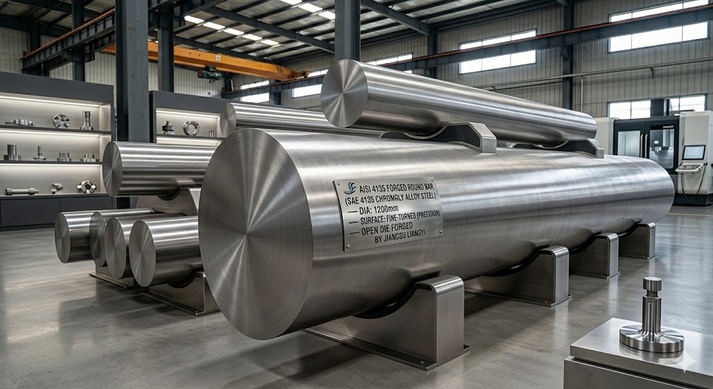 AISI 4135 Forged Round Bar
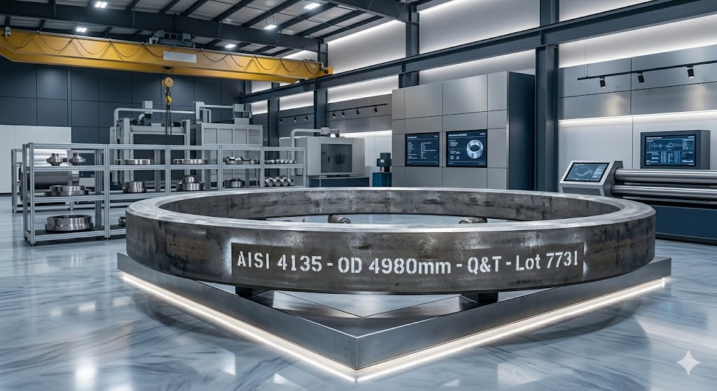 AISI 4135 Seamless Rolled Ring
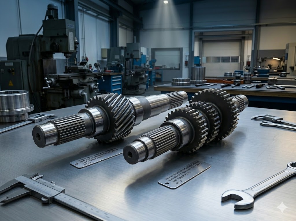 AISI 4135 Forged Gear Shaft
Custom AISI 4135 Forged Product Forms We Supply
Every geometry we produce from SAE 4135 alloy steel starts with a carefully designed forging process — not machining from oversized bar stock. This distinction matters for your engineering team because forged parts carry a continuous, unbroken grain flow aligned with the intended stress directions of the final component, while bar-cut parts have a grain structure that is indifferent to your part's load paths. The result in service is predictably superior fatigue life and impact resistance. Below is the full range of AISI 4135 forged product forms we manufacture and supply to global industrial customers:
1. AISI 4135 Forged Round Bars, Square Bars & Stepped Bars
Our AISI 4135 forged bars are produced by open-die pressing from ingot or billet, achieving a controlled forging ratio of typically 3:1 to 6:1 to guarantee adequate grain refinement and homogeneous through-section properties. Available in solid round, square, flat, and rectangular cross-sections, as well as multi-step profiles (stepped bars) that closely approach the net shape of shafts, spindles, or mandrels, reducing downstream machining stock and cycle time. Standard supply condition: rough-turned and centre-drilled to a machining allowance of 5–15mm per side, or rough forged with UT-inspected cross-sections. Maximum forged bar diameter: 1,200 mm. Length: up to 8,000 mm per piece. Weight: 30 KG to 15,000 KG per bar.
2. AISI 4135 Seamless Rolled Rings & Gear Rings
Our AISI 4135 seamless rolled rings are produced on our in-house radial-axial ring rolling mill, starting from upset-and-pierced forged preforms. The ring rolling process guarantees a continuous, circumferential grain flow around the ring circumference — the ideal microstructural orientation for ring components subject to hoop stress, bending fatigue, and contact stress. We produce rings in rectangular cross-section (flat rings), profile cross-section (gear ring blanks, flanged rings, L-section bearing races), and near-net-shape profiles reducing gear hobbing stock. Maximum outer diameter: 5,000 mm. Maximum height: 1,500 mm. Wall thickness: from 30 mm upward. Weight: 30 KG to 30,000 KG per ring. Standard delivery: rough-turned ID/OD, UT-cleared, heat-treated to your hardness specification.
3. AISI 4135 Forged Gear Shafts, Pinion Shafts & Spindles
SAE 4135 gear shafts and pinion shafts are among our highest-volume product forms, supplied to gearbox manufacturers, cement mill operators, mining equipment OEMs, and power generation system integrators worldwide. Our shaft forging process uses controlled multi-heat reduction passes to build forging fiber along the shaft axis — precisely the grain orientation required for maximum bending fatigue resistance in rotating shafts under alternating loads. We supply shafts rough-forged, semi-machined (journals turned, keyways cut, center-holes drilled), or fully finish-machined with gear profiles hobbed/ground to DIN 3960/3961 or AGMA 2000/2001 accuracy grades. Maximum shaft length: 12,000 mm. Maximum forged diameter: 1,200 mm. Shaft OD tolerances: h6/h7/h8 for journals; k6/m6 for interference fit seats.
4. AISI 4135 Forged Discs, Flanges & Valve Bodies
For disc and flange geometries, we use upset forging (pancake forging) to maximize the forging reduction ratio in the axial direction, producing a radial grain flow pattern that improves pressure-face strength and resistance to delamination under cyclic axial load. Our AISI 4135 forged discs and flanges serve oilfield wellhead flanges (API 6A / ASME B16.5 compatible), turbine disc blanks, pump impeller forgings, and gearbox housing flanges. Maximum disc diameter: 2,500 mm. Maximum disc height: 800 mm. Machining: rough bored and faced, or fully machined to drawing with bolting, sealing, and fit dimensions held to H7 or tighter.
5. AISI 4135 Hollow Forgings, Sleeves & Barrel Blanks
Hollow forging — where a pierced preform is mandrel-forged to a tubular geometry — produces AISI 4135 hollow forgings with wall properties superior to any drilled bar, because the grain matrix flows circumferentially around the bore rather than being severed by drilling. We supply hollow round bars, sleeves, bushings, cylinder blanks, hydraulic cylinder barrel blanks, and casing components. Maximum OD: 1,200 mm. Minimum ID: 150 mm. Maximum wall thickness: 400 mm. Length: up to 6,000 mm. Bore surface finish: rough bored to machining allowance, or honed to Ra 0.4 μm for hydraulic cylinder applications.
6. Fully Custom OEM / ODM AISI 4135 Forged Components
Beyond standard shapes, we accept completely bespoke custom OEM forging orders covering any geometry that can be produced by open-die or near-net forging and subsequent CNC machining — including eccentric shafts, crankshafts, yokes, connecting rods, pintle pins, and complex multi-diameter stepped profiles. Our engineering team reviews your 2D/3D drawings (accepted formats: DWG, DXF, PDF, STEP, IGES, SolidWorks, AutoCAD), advises on the optimal forging approach and machining allowance, and prepares a dedicated forging process specification (FPS) before production begins. All custom parts are produced with first-article inspection (FAI) reports and full dimensional records retained for 10 years.
Explore our full range of forged steel products and all forging material grades we work with for global industrial customers.
Industrial Applications & Use Cases of AISI 4135 Forgings
AISI 4135 (UNS G41350) is chosen by design engineers when a component must simultaneously satisfy three competing demands: high tensile strength for load-carrying capacity, good impact toughness to survive shock loads or misuse events, and sufficient hardenability to get consistent properties through a large cross-section. Standard carbon steels fail the hardenability requirement for sections above ~50mm diameter; high-alloy steels meet strength targets but at significantly higher material and machining cost. AISI 4135 is the cost-efficient solution that spans these requirements — which is precisely why it appears across industries as diverse as deepwater oil & gas, open-pit mining, wind turbine drivetrains, and locomotive traction systems.
From our direct experience supplying AISI 4135 forged parts to end-users and OEMs across these sectors, the following application breakdown reflects real-world engineering requirements, failure modes we have helped customers solve, and the component geometries that benefit most from the open-die forging process in this alloy:
Oil & Gas and Offshore Subsea Industry
Oilfield equipment designers specify SAE 4135 forgings for components that must simultaneously resist internal pressure (sometimes exceeding 15,000 psi / 103 MPa), external corrosion, and impact loads from well control events. API 6A — the governing specification for Christmas tree and wellhead equipment — mandates material traceability, impact testing at low temperatures (typically −60°F / −51°C for PSL 2/3 equipment), and hardness verification that is directly satisfied by our quench-and-tempered 4135 forgings with EN 10204 3.1 MTCs. Following are main applications we have supplied:
- Wellhead and Christmas tree bodies: Casing heads, tubing heads, casing hangers, tubing spools, frac adapter spools, and crossover spool bodies — where the combination of high pressure rating and weld-neck hub forging geometry makes open-die forged 4135 the standard material of choice
- Drilling system components: Mud pump power-end crankshafts and crosshead pins (subject to high-cycle bending fatigue in abrasive drilling mud environments), downhole mud motor drive shafts (requiring uniform hardness through large diameters), top-drive gear shafts and spindle assemblies, and drill collar forgings for directional drilling tool-string assemblies
- High-pressure valve forgings: Gate valve bodies, bonnet forgings, valve stems, ball valve bodies (API 6D class), choke valve bodies, and plug valve forgings for flowline and manifold service. The forged grain matrix deletes the porosity present in cast valve bodies, which is important for compliance with API 598 pressure test requirements
- Blowout preventer (BOP) components: BOP body forgings, ram block housings, and hydraulic actuator cylinder barrels — where AISI 4135 Q&T to 120 ksi (827 MPa) tensile strength with full Charpy impact testing at −20°F is a standard procurement requirement
- Subsea and offshore structural forgings: Anchor winch drum stubs, mooring tensioner body forgings, riser tensioner frame components, and connector hub forgings for subsea trees and manifolds
Need AISI 4135 forgings for oil and gas equipment subject to API 6A or NACE MR0175 material requirements? Contact our engineering team — we have experience supplying material meeting these requirements with full EN 10204 documentation. Note: API 6A monogram licensing is held by the equipment manufacturer, not the forging supplier. We supply forged material and components compliant with the material requirements of API 6A and NACE MR0175 / ISO 15156, subject to specification review.
Mining & Mineral Processing Industry
Mining equipment operates under some of the most severe loading conditions in industrial engineering: crusher eccentric shafts experience combined bending and torsion with sudden overload spikes when tramp iron enters the crushing chamber; dragline camshafts must resist multi-axis fatigue over equipment lives measured in decades. AISI 4135 forgings are preferred over carbon steel (insufficient hardenability in large cross-sections) and stainless alloys (unnecessary cost for these wear-structural applications) in the following mining equipment components:
- Crusher drive components: Main eccentric shafts and main spindles for gyratory and cone crushers (typically 300–800mm diameter, 2,000–8,000mm length), jaw crusher pitman shafts and toggle assemblies, hammer mill rotor shafts, and VSI crusher rotor hub assemblies. Our forged 4135 eccentric shafts are supplied rough-turned and UT-cleared, with journals finish-ground to h6 bearing seat tolerances
- Excavator and shovel components: Slewing bearing ring blanks for large mining excavators (OD 2,000–4,500mm), dragline centre pintle forgings, electric shovel crowd gear shafts and swing gear pinion shafts, and cable shovel dipper handle pins — all applications where the continuous grain flow from the forging process is not just beneficial but often specified in OEM procurement documents
- Mine hoist and conveyor systems: Rope drum shaft forgings for friction hoists and drum hoists (critical safety components subject to mandatory third-party inspection), conveyor drive pulley shaft forgings, and idler roll axles for heavy-duty overland conveyors serving bulk mineral applications
- Grinding mill components: Pinion shaft forgings for SAG mills, ball mills, and rod mills — where the gear end must satisfy surface hardness requirements for gear cutting (typically 25–30 HRC) while the bearing journals remain at a softer, more machinable condition, achieved by our selective tempering capability
Need AISI 4135 crusher shaft or slewing ring forgings? Send your drawing — we'll respond with a detailed quotation within 24 working hours.
Cement, Lime & Bulk Material Processing Industry
Rotary kilns, cement mills, and bulk material processing equipment impose continuous, cyclical loads on large forged components over operational lifetimes of 15–25 years without replacement. The selection of SAE 4135 forgings in these applications is driven by the combination of case-hardenability (achieved through induction hardening of gear tooth flanks on forged pinion shafts), core toughness that prevents brittle fracture during cold start-up, and fatigue strength adequate for 10⁸ to 10¹⁰ load cycles over service life. Key components include:
- Kiln and mill pinion shafts: Open-gear drive pinion shaft forgings for rotary cement kilns, clinker coolers, raw mills, and ball mills, typically ∅300–700mm shaft body with integral gear journal. Supplied with grain flow optimized by controlled forging reduction, then induction-hardened on gear flank surfaces to 55–60 HRC with a tough 4135 core at 28–34 HRC
- Riding rings (tyres) and support rollers: Seamless rolled ring forgings in AISI 4135 for rotary kiln riding rings (OD 2,000–5,000mm), where the circumferential grain flow from ring rolling provides superior resistance to contact fatigue under the continuous rolling contact with support rollers
- Rotary dryer and cooler components: Gear rings, riding ring forgings, and trunnion shaft assemblies for rotary dryers, granulators, and clinker coolers in fertilizer, mining, and cement processing plants
Power Generation Industry (Wind, Hydro & Thermal)
Power generation equipment demands materials with a well-defined and consistent fatigue endurance limit — a property that quench-and-tempered AISI 4135 forgings deliver reliably. For wind turbine gearbox components in particular, the IEC 61400-4 design standard requires materials with documented Charpy impact values, fatigue S-N data, and full MTC certification — all routinely provided with our 4135 forgings. Applications include:
- Wind turbine drivetrain components: High-speed and intermediate shaft forgings, sun gear shaft blanks, planet carrier pin shafts, and ring gear blanks for multi-stage planetary gearboxes in 1.5 MW to 6+ MW wind turbines. The combination of 4135's hardenability and toughness makes it the preferred material for through-hardened, case-carburized, or nitrided gear shaft applications in IEC-compliant wind turbine gearboxes
- Hydro turbine main shafts: Large-diameter forged shafts for Francis, Kaplan, and Pelton turbines, where shaft diameter may range from 500mm to 1,500mm and forging weight from 5 to 30 metric tons. Our multi-heat forging protocol achieves the deep, uniform hardenability required for through-section hardness consistency in these heavy-section components
- Thermal and gas power plant components: Generator rotor stub shaft forgings, turbine disc blanks, labyrinth seal ring forgings, and coupling flanges for steam and gas turbine sets — components that must maintain dimensional stability under thermal cycling, making the low residual stress achieved through our post-forge stress relief heat treatment essential
General Industrial Machinery & Heavy Equipment
Across all categories of industrial gearboxes, hydraulic systems, and processing machinery, AISI 4135 alloy steel forgings are the default specification for medium-to-heavy shafts, gear blanks, and structural components. Our supply to this sector spans:
- Industrial gearbox components: Gear shaft blanks, pinion shaft forgings, ring gear blanks, output shaft forgings, and gearbox housing flange forgings for standard parallel-shaft, bevel, helical, and planetary gearboxes used in conveyors, mixers, extruders, and industrial drives. Gear teeth are typically precision-cut by our customers' gear-cutting departments from our accurately turned and UT-cleared forged blanks
- Hydraulic cylinder components: Cylinder barrel blanks, piston rod forgings, and end cap forgings for heavy-duty hydraulic cylinders used in construction machinery, marine deck equipment, and industrial press systems. Our hollow-forged cylinder barrels eliminate the longitudinal porosity that plagues drilled-bar hydraulic cylinders, critical for cylinders operating at 350+ bar working pressure
- Metals processing equipment: Cold mill and hot mill roller shaft forgings, mandrel forgings for tube rolling mills, and winder/decoiler drum shafts for steel processing lines — where the combination of hardness, toughness, and dimensional stability under high torque is essential
- Sugar mill and agro-processing equipment: Mill roller shaft forgings (typically 300–600mm OD, 2,000–4,500mm length), coupling flange forgings, and pinion shaft assemblies for cane crushing and diffuser drive systems
- Environmental and process equipment: Atomizer shaft forgings for wet flue gas desulfurization (WFGD) absorber sprayer systems, rotary valve shaft assemblies for pneumatic conveying systems, and agitator shaft forgings for wastewater treatment equipment
Transportation, Railway & Marine Industry
Transportation applications impose strict certification and traceability requirements on forged components — railway standards (EN 13261, AAR M-107), marine classification (DNV GL, Lloyd's Register, ABS), and automotive OEM quality systems all specify material testing and documentation requirements that align directly with our standard MTC and inspection package. Our SAE 4135 forged parts serve:
- Railway traction and transmission components: Locomotive gear shaft forgings, traction motor suspension tube forgings, bogie pivot pin assemblies, axle gear box pinion shaft forgings — all subject to EN or AAR material certification requirements that our 4135 Q&T process routinely satisfies
- Commercial vehicle and off-highway machinery: Ring gear and planet gear carrier forgings for heavy truck rear axle differentials, transfer case shaft forgings, and concrete mixer drum drive gear ring blanks
- Marine propulsion and deck equipment: Propeller shaft forgings, marine gearbox pinion shafts, anchor windlass drum shafts, and mooring winch drive shaft forgings. Our forgings can be supplied with EN 10204 3.2 third-party inspection by the customer's nominated marine classification surveyor (ABS, DNV GL, Lloyd's Register, Bureau Veritas, etc.) arranged at additional cost — final class certification is issued by the classification society upon their surveyors' witnessing of the testing.
AISI 4135 (UNS G41350) Alloy Steel Chemical Composition
The composition of AISI 4135 alloy steel is precisely defined by the AISI/SAE standard to achieve a specific balance of hardenability, strength, and toughness in forged and heat-treated condition. Unlike commodity carbon steels, every element in 4135 performs a specific metallurgical function. Knowing the function of each alloying element allows engineers to predict the behavior of the material in service and choose the heat treatment parameters according to their section size and application needs. Following is the full chemical composition per AISI/SAE specification :
| Chemical Element | Content Range (Weight %) | Metallurgical Function in AISI 4135 |
|---|
| Carbon (C) | 0.330 – 0.380 | Primary hardening element. Controls the maximum achievable hardness after quenching (theoretical max ~56 HRC at 0.38% C). The 0.33–0.38% range positions 4135 between 4130 (lower strength) and 4140 (higher hardness but reduced toughness), giving an optimal strength-toughness balance for heavy-section forgings. |
| Chromium (Cr) | 0.80 – 1.10 | Significantly improves hardenability by suppressing the pearlite transformation nose on the CCT diagram, allowing martensite formation at lower cooling rates and in larger cross-sections. Chromium also increases resistance to oxidation at elevated temperatures and improves wear resistance by forming chromium carbides in the microstructure. |
| Molybdenum (Mo) | 0.15 – 0.25 | The main element for deleting temper embrittlement (a phenomenon where steels slow-cooled through 375–575°C lose toughness). Molybdenum suppresses the segregation of tramp elements (P, Sn, As, Sb) to prior austenite grain boundaries that causes embrittlement. It also refines grain size, improves creep resistance at elevated temperature, and improves hardenability beyond what chromium alone provides. |
| Manganese (Mn) | 0.70 – 0.90 | Acts as a deoxidizer and desulfurizer during steelmaking, fixing sulfur as MnS inclusions (which are far less harmful than FeS at grain boundaries). Manganese also contributes to hardenability and solid-solution strengthening, lowering the martensite start temperature (Ms) slightly to improve through-section hardness consistency. |
| Silicon (Si) | 0.15 – 0.35 | Functions primarily as a deoxidizer in steelmaking (removing dissolved oxygen that would otherwise form oxide inclusions). Silicon also slightly increases elastic limit and tensile strength through solid-solution strengthening, and raises the recrystallization temperature — beneficial for keeping fine grain size during multi-pass forging operations at the upper temperature range. |
| Sulfur (S) | ≤ 0.040 | Controlled as a tramp element. In combination with Mn, sulfur forms elongated MnS inclusions that improve machinability but reduce transverse ductility and impact energy. For important forging applications, we specify and verify S ≤ 0.020% from our qualified steel mill suppliers, well below the standard maximum limit. |
| Phosphorus (P) | ≤ 0.035 | Strictly controlled as a harmful impurity. Phosphorus segregates to austenite grain boundaries and dramatically reduces impact toughness, especially in the ductile-to-brittle transition temperature range. Our standard melt practice achieves P ≤ 0.020% for forging applications requiring low-temperature Charpy impact certification. |
| Iron (Fe) | Balance (~97.33 – 97.87) | Ferrite-forming matrix element. The iron lattice provides the base microstructure (ferrite → austenite → martensite transformation) that all other alloying elements modify. The precise iron balance makes sure the alloy system operates within the defined hypoeutectoid region for predictable phase transformation behavior during heat treatment. |
Every incoming heat of AISI 4135 billet is verified against the steel mill's chemical test certificate using our in-house optical emission spectrometer (OES), and a re-analysis is performed on a sample from the finished forging to confirm composition integrity through the forging process. Both sets of chemical data are reported on our EN 10204 3.1 Mill Test Certificate. For customers with tighter compositional requirements — for example, P ≤ 0.020% and S ≤ 0.020% for subsea or low-temperature service — we can specify a narrowed chemistry range with our qualified steel mill suppliers at the time of material ordering.
AISI 4135 International Grade Equivalents & Cross-Reference
AISI 4135 (SAE 4135, UNS G41350) is a globally recognized chromium-molybdenum alloy steel grade. The following table shows the closest equivalent designations across the main international standards, to help engineers worldwide to specify the right material for their projects:
Key equivalents at a glance: AISI 4135 ≈ DIN 34CrMo4 (Germany) ≈ EN 1.7220 (Europe) ≈ JIS SCM435 (Japan) ≈ GB 35CrMo (China) ≈ BS 708M40 (UK, nearest)
| Standard System | Country / Region | Grade Designation | Notes |
|---|
| AISI / SAE | USA | AISI 4135 / SAE 4135 | Reference grade; UNS G41350 |
| DIN | Germany | 34CrMo4 | Very close equivalent; slightly lower Mn |
| EN (European) | Europe (EU) | 1.7220 (34CrMo4) | EN 10083-3 standard |
| JIS | Japan | SCM435 | JIS G4105; very close equivalent |
| GB | China | 35CrMo | GB/T 3077; minor composition variation |
| BS | United Kingdom | 708M40 / 708A37 | Near equivalent; confirm with datasheet |
| GOST | Russia / CIS | 35KhM | Approximate equivalent |
| NF | France | 34CD4 | French standard equivalent |
* Grade equivalents are approximate based on chemical composition similarity. Always verify final suitability against your project specification, relevant standard, and our MTC data before ordering.
Heat Treatment Process for AISI 4135 Forging Parts
Heat treatment is not a post-processing step for AISI 4135 forgings — it is an integral part of the manufacturing engineering that determines the final mechanical properties of your component. The same forged piece of 4135 can be delivered as-forged (soft, easily machinable), annealed (fully recrystallized, ~180 HB), normalized (fine-grained, ~200 HB), or quenched-and-tempered (high strength, 28–40 HRC depending on tempering temperature). Selecting the correct heat treatment condition for your application — and executing it with tight process control — is where our 28 years of experience translates directly into parts that perform consistently in service.
All heat treatment at Jiangsu Liangyi is performed in our in-house, calibrated furnaces equipped with programmable multi-zone temperature controllers, chart recorders, and thermocouple validation. Every heat treatment batch is accompanied by a heat treatment record (HTR) document that forms part of our EN 10204 3.1 MTC package. Our standard AISI 4135 heat treatment process parameters are as follows:
Stage 1: Hot Forging Temperature Control
Hot forging of AISI 4135 begins with billet heating to a maximum furnace setpoint of 1205°C (2200°F) — the upper safe limit before incipient melting of low-melting-point phases at prior austenite grain boundaries. Forging is completed above the austenite-to-ferrite transformation temperature (approximately 900°C / 1650°F for 4135) to avoid deformation-induced ferrite formation, which would create a duplex, non-uniform microstructure. The minimum forging finish temperature is controlled to ensure that any phase transformation occurring during final forging passes takes place in the full austenite field, producing the equiaxed, fine-grained structure that responds predictably to subsequent heat treatment. Forging reduction ratios of at least 3:1 (and typically 4:1 to 6:1) are maintained to ensure adequate grain refinement and closure of any residual solidification porosity from the original ingot.
Stage 2: Post-Forge Annealing or Normalizing
After forging and initial air cooling, most AISI 4135 forgings receive either a full anneal (790–845°C / 1454–1553°F, furnace-cooled at a controlled rate of ≤15°C/hour through the eutectoid range to prevent pearlite coarsening) or a normalizing treatment (870–900°C / 1598–1652°F, air-cooled). Annealing produces the softest, most machinable condition (typically 163–229 HB) and is the standard delivery condition for customers who perform their own final machining and heat treatment. Normalizing produces a finer, more uniform pearlitic microstructure (typically 170–220 HB) with higher strength than fully annealed, and is often specified as the delivery condition for rough-machined blanks that will receive final Q&T by the customer. Both treatments also relieve forging residual stresses, preventing dimensional movement during subsequent machining operations.
Stage 3: Hardening (Austenitizing + Quenching)
For customers who need quenched-and-tempered (Q&T) forgings, the hardening process begins with austenitizing at 845–870°C (1553–1598°F) for a soak time calculated as 1 hour minimum plus approximately 1 hour per 25mm of ruling section — guaranteeing full, uniform austenite formation throughout the cross-section before quenching. Quenching medium for AISI 4135 is typically oil (or polymer quenchant at controlled concentration and temperature), selected to provide sufficient cooling rate to achieve martensite transformation throughout the ruling section while avoiding the thermal shock of water quenching that would risk quench cracking in heavier sections. The Grossman hardenability of 4135 (DI ≈ 100–140mm) means that through-hardening to a martensitic microstructure can be reliably achieved in sections up to approximately 75–100mm diameter after oil quenching — a significant advantage over plain carbon steels.
Stage 4: Tempering
Quenched 4135 in the as-quenched condition has very high hardness (typically 54–58 HRC) but dangerously low toughness — it is too brittle for engineering use. Tempering is the critical final step that converts the as-quenched martensite into tempered martensite, simultaneously reducing hardness (and thus brittleness) and increasing ductility and impact energy to engineering-useful levels. The tempering temperature is the primary variable controlling final mechanical properties:
- High tempering temperature (580–680°C): Produces a lower tensile strength (750–900 N/mm²) with high ductility and impact energy — the standard specification for heavily loaded structural components, shaft forgings, and components requiring low-temperature Charpy impact certification (such as API 6A PSL 2/3 wellhead forgings tested at −60°F)
- Medium tempering temperature (450–580°C): Achieves intermediate tensile strength (900–1100 N/mm²) with good toughness — typical for general industrial gear shaft forgings, gearbox components, and mining equipment parts
- Lower tempering temperature (250–400°C): Produces maximum hardness and strength (1100–1200 N/mm²) with acceptable but reduced toughness — used for components requiring high surface hardness before final machining, or where the application load is predominantly compressive rather than impact-tensile
A critical process control point: AISI 4135 contains sufficient molybdenum (0.15–0.25%) to suppress temper embrittlement, but all tempering cycles are designed to either avoid the embrittlement range (375–575°C) or cool rapidly through it after tempering at higher temperatures. This is a process discipline that distinguishes properly manufactured 4135 forgings from lower-quality alternatives where tempering protocols are not rigorously controlled. All tempering is performed in calibrated furnaces with chart-recorded temperature verification and documented soak times calculated from part ruling section.
Supplementary Heat Treatments Available
- Stress relieving: 550–600°C furnace soak followed by slow cooling — performed after rough machining on precision components to eliminate machining-induced stresses before final cuts
- Induction hardening: Selective surface hardening of gear tooth flanks, journal surfaces, or cam profiles to 55–62 HRC while maintaining the tough Q&T core structure — available as a combined service with our machining operations for pinion shafts and gear shaft blanks
- Nitriding (gas or plasma): Available for AISI 4135 components requiring case depths of 0.2–0.6mm to improve surface hardness (650–750 HV) and fatigue performance without the quenching distortion of induction hardening
Mechanical Properties of AISI 4135 Forged Steel
The mechanical properties of quench-and-tempered AISI 4135 forgings are section-size dependent — a fundamental characteristic of any hardenable alloy steel that reflects the effect of cooling rate on microstructure throughout large cross-sections. In smaller sections (≤ 16mm), the surface and core cool at similar rates, producing a uniformly martensitic microstructure throughout the section and the highest achievable strength values. In larger sections (100–250mm), the core cooling rate is significantly slower than the surface, producing mixed microstructures (martensite + bainite + ferrite-pearlite at the core in very large sections) with progressively lower strength and higher ductility. This section-size effect is why AISI 4135 forgings used in large structural components — for example, a 500mm diameter crusher eccentric shaft — are designed with safety factors that reflect core, not surface, mechanical properties.
The following table presents typical mechanical properties for AISI 4135 forged parts after standard quench and temper heat treatment, per DIN EN 10083-3 (34CrMo4 / 1.7220) as the reference standard. Actual guaranteed values are confirmed on the EN 10204 3.1 MTC accompanying each delivery. ASTM A322 / SAE J1397 equivalent properties are also available on request for North American procurement specifications:
| Section Size (mm) | 0.2% Offset Yield Strength Rp0.2 (N/mm²) Min. | Tensile Strength Rm (N/mm²) | Elongation A5 (%) Min. | Reduction of Area Z (%) Min. | ISO-V Notch Impact Energy (J) Min. (20°C) | Approx. Hardness (HB) |
|---|
| < 16 | 800 | 1000 – 1200 | 11 | 45 | 35 | 294 – 352 |
| 16 – 40 | 650 | 900 – 1100 | 12 | 50 | 40 | 263 – 321 |
| 40 – 100 | 550 | 800 – 950 | 14 | 55 | 45 | 235 – 277 |
| 100 – 160 | 500 | 750 – 900 | 15 | 55 | 45 | 217 – 263 |
| 160 – 250 | 450 | 700 – 850 | 15 | 60 | 45 | 207 – 248 |
Engineering notes on using this data:
- These values are for standard Q&T condition with a high tempering temperature (approx. 580–650°C). Lower tempering temperatures can achieve higher tensile strength (up to 1,300 N/mm² in small sections) at reduced impact energy — we will specify the optimal tempering condition for your application on request.
- Test specimens for mechanical property verification are taken from the sacrificial test extension forged integrally with the part, at 1/4 T depth from the surface for ring and disc forgings, or from the center of a separately forged representative coupon for shaft sections larger than 250mm ruling section.
- For applications requiring low-temperature impact certification (e.g., API 6A PSL 3 at −60°F / −51°C, or Charpy testing at −20°C for subsea structural components), we can design a heat treatment cycle and test protocol to achieve 27 J minimum CVN at the specified test temperature — please specify this requirement at the time of enquiry.
- Hardness values (HB) listed above are approximate conversions from tensile strength using the Brinell hardness correlation in EN ISO 18265. Actual hardness is verified on each forging by Brinell hardness testing at a minimum of 3 points per piece, reported on the MTC.
Physical Properties of AISI 4135 Steel
The following table lists the key physical properties of AISI 4135 chromium-molybdenum alloy steel in the annealed or normalized condition. These properties are important for thermal analysis, stress modeling, and design calculations:
| Physical Property | Value | Unit |
|---|
| Density | 7.85 | g/cm³ (7850 kg/m³) |
| Melting Point (Liquidus) | ~1455 | °C (~2651°F) |
| Elastic Modulus (Young's Modulus) | 205 | GPa |
| Shear Modulus | 80 | GPa |
| Poisson's Ratio | 0.29 | — |
| Thermal Conductivity (at 25°C) | 42.7 | W/(m·K) |
| Specific Heat Capacity | 473 | J/(kg·K) |
| Coefficient of Thermal Expansion (20–100°C) | 12.3 | ×10⁻⁶ /°C |
| Electrical Resistivity (at 20°C) | ~0.22 | μΩ·m |
AISI 4135 vs. AISI 4140 vs. AISI 4130 — Grade Comparison
The choice of the proper grade of chromium-molybdenum steel is important for performance and cost. The table below shows how AISI 4135 compares with closely related AISI 4140 and AISI 4130 grades in main parameters:
| Parameter | AISI 4130 | AISI 4135 | AISI 4140 |
|---|
| Carbon Content (%) | 0.28 – 0.33 | 0.33 – 0.38 | 0.38 – 0.43 |
| Chromium (%) | 0.80 – 1.10 | 0.80 – 1.10 | 0.80 – 1.10 |
| Molybdenum (%) | 0.15 – 0.25 | 0.15 – 0.25 | 0.15 – 0.25 |
| Max. Tensile Strength (Q&T) | ~950 N/mm² | ~1200 N/mm² | ~1300 N/mm² |
| Toughness / Ductility | Excellent | Very Good | Good |
| Hardenability | Moderate | High | Very High |
| Weldability | Good | Moderate (pre-heat recommended) | Fair (pre-heat required) |
| Machinability | Good | Good | Good |
| Typical Forging Applications | Aerospace, thin-wall pressure vessels | Gear shafts, oil & gas, mining, heavy machinery | High-strength shafts, tooling, dies |
| DIN Equivalent | 25CrMo4 (1.7218) | 34CrMo4 (1.7220) | 42CrMo4 (1.7225) |
Summary: AISI 4135 is the optimal balance between the lighter 4130 (better weldability, lower strength) and the heavier 4140 (higher strength, less toughness). It is the best choice material when both high fatigue resistance and good impact toughness are required in thick-section forgings — for example, gear shafts, drilling components, and heavy machinery drive parts.
Strict Quality Control for AISI 4135 Forged Parts
Quality at Jiangsu Liangyi is not a department — it is a manufacturing discipline built into every step of the production sequence, from raw material choice through final dimension test before packing. For AISI 4135 forged parts, where the mechanical property specification is entirely dependent on the quality of the forging process and heat treatment execution, this integrated quality approach is essential. The following describes our actual quality control sequence, the specific tests performed, the equipment used, and the documentation generated at each stage:
Stage 1 — Raw Material Incoming Inspection
All AISI 4135 steel billet and ingot material is sourced from qualified steel mill suppliers that operate EAF + LF + VD (electric arc furnace + ladle refining + vacuum degassing) production routes. We review and retain the steel mill's original chemical test certificate for every incoming heat. Each heat is then re-verified using our in-house optical emission spectrometer (OES) — any heat with chemical composition outside AISI/SAE specification is rejected before entering the forging process. Incoming billet is checked visually and dimensionally for surface condition, straightness and cross section size conformance. For new supplier qualification, macro-etch tests on billet cross-sections are carried out to confirm the absence of centre segregation, pipe and excessive inclusions.
Stage 2 — Forging Process Monitoring
Every furnace batch is monitored with calibrated digital pyrometers to track forging temperatures in real time. For multi-pass open-die forging processes, press load and stroke data are fully recorded. The forging ratio (cross-section reduction) of each part is calculated and documented to meet the minimum reduction requirement, generally 3:1.During ring rolling, laser measuring systems continuously monitor outer diameter, inner diameter and height dimensions. This ensures the dimensional accuracy of ring blanks right after rolling and before cooling down.
Stage 3 — Heat Treatment Records
All heat treatment cycles are executed in programmed, calibrated furnaces with continuous chart recording. The heat treatment record (HTR) document captures: furnace ID number, batch identification, loading date/time, temperature setpoints vs. actual temperature (with deviation alerts), soak time, quench medium temperature, quench duration, and tempering parameters. Furnace calibration certificates (traceable to national standards) are kept and renewed annually. This HTR document is a mandatory attachment to our EN 10204 3.1 MTC for all Q&T deliveries.
Stage 4 — Chemical Composition Re-verification
A sample cut from each finished forging (or from a test ring forged from the same heat simultaneously) is re-analyzed by OES spectrometry to confirm that no composition drift occurred during the forging process (possible if, for example, decarburization is suspected). Results are compared to the steelmaker's mill cert and both sets of chemical data are reported on the MTC, providing dual-source chemical traceability.
Stage 5 — Mechanical Properties Testing
Tensile testing (yield strength Rp0.2, ultimate tensile strength Rm, elongation A5, reduction of area Z) is performed on standard round test specimens per ISO 6892-1 (equivalent to ASTM E8), machined from test material taken at ¼T depth from the forging surface (for discs and rings) or from the center of the forging (for solid bars and shafts in the ruling section range). Charpy V-notch impact testing (ISO 148-1 / ASTM E23) at 20°C is standard; low-temperature testing (−20°C, −40°C, −60°F / −51°C) is available on request. Hardness testing (Brinell, HBW per ISO 6506 / ASTM E10) is performed on each forging piece at a minimum of three surface locations, with results reported per piece on the MTC.
Stage 6 — Ultrasonic Testing (UT)
All AISI 4135 forgings above a defined size threshold (typically > 50kg, or as specified by the customer) undergo full volumetric ultrasonic testing per EN 10228-3 (Class 3 or 4 as standard; Class 5 for critical applications) or ASTM A388 using calibrated UT equipment with straight-beam and angle-beam probes. Forgings are scanned on 100% of accessible surfaces with a scan index ≤ half the transducer diameter. Any indication exceeding the specified rejection level (typically equivalent to a 2mm flat-bottom hole reflector at the test frequency and gain used) results in rejection or rework of the affected area. UT operators hold valid qualification certificates to the relevant NDT personnel certification standard.
Stage 7 — Surface NDT (MT / PT)
For forgings in the as-machined or rough-turned condition, magnetic particle testing (MT, per EN ISO 17638 or ASTM E709) is performed on all accessible surfaces to detect surface and near-surface discontinuities — forging laps, seams, quench cracks, or grinding burns. For non-magnetic or austenitic applications (rare for 4135 but applicable to cladded components), liquid penetrant testing (PT, per EN ISO 3452-1 or ASTM E165) is used as an alternative. MT results are typically to acceptance level ASME VIII Div. 1 App. 6, or the customer's specification as applicable.
Stage 8 — Dimensional Inspection
Full dimensional verification is performed by our metrology team using calibrated instruments: vernier calipers, micrometers, bore gauges, digital height gauges, and coordinate measuring machine (CMM) for complex geometries. All important dimensions (bearing seat diameters, bore diameters, shoulder positions, runout/concentricity, surface finish Ra values) are measured and recorded on the dimensional inspection report (DIR), which accompanies the MTC in the final documentation package.
Final Documentation Package
Each shipment of AISI 4135 forgings from Jiangsu Liangyi includes: EN 10204 3.1 Mill Test Certificate (or 3.2 with third-party witness inspection by SGS, BV, TÜV, or Intertek at additional cost), heat treatment records, dimensional inspection report, UT test report, MT/PT test report (if applicable), packing list with piece marking cross-reference, and a copy of our ISO 9001:2015 certification. All documentation is available in English, and in Chinese upon request. Electronic document sets (PDF) are transmitted by email prior to or with shipment.
Learn more about our advanced production and inspection equipment — including our hydraulic press capacities, ring rolling equipment, heat treatment furnace inventory, and NDT instrumentation.
Frequently Asked Questions About AISI 4135 Forgings
AISI 4135 (also designated SAE 4135, UNS G41350, DIN 34CrMo4, or EN 1.7220) is a medium-carbon chromium-molybdenum alloy steel containing 0.33–0.38% carbon, 0.80–1.10% chromium, and 0.15–0.25% molybdenum. It belongs to the SAE 41xx "chromoly" series — a family of alloy steels widely used in forging applications due to their excellent hardenability, strength-toughness balance, and heat treatability.
What distinguishes AISI 4135 within the Cr-Mo family is its position in the carbon range. Compared to the lower-carbon 4130 (0.28–0.33% C), 4135 achieves higher strength after quenching and tempering, particularly in sections above 40mm. Compared to the higher-carbon 4140 (0.38–0.43% C) and 4142 (0.40–0.45% C), 4135 offers meaningfully better impact toughness and weldability — important for components subject to dynamic or shock loading, or where weld repairs may be required in service. The molybdenum content (0.15–0.25%) is especially important in forging applications: it suppresses temper embrittlement (a phenomenon where steels slow-cooled through the 375–575°C range lose toughness), refines grain size, and enhances the hardenability already contributed by chromium. Together, Cr and Mo allow 4135 to achieve through-hardening in sections up to approximately 75–100mm diameter after oil quenching — a capability that plain carbon steels like 1045 or 1060 cannot match.
The central difference is carbon content: AISI 4135 contains 0.33–0.38% C, while AISI 4140 contains 0.38–0.43% C. This ~0.05% difference has practical engineering consequences that become significant in forging applications:
Strength: AISI 4140 can achieve approximately 5–8% higher tensile strength than 4135 in the same section size after identical Q&T treatment — approximately 950–1,300 N/mm² vs. 900–1,200 N/mm² for sections under 40mm. For applications where maximum strength is the primary requirement, 4140 is preferred.
Toughness: AISI 4135 consistently outperforms 4140 in Charpy V-notch impact energy, particularly at lower temperatures. For components subject to dynamic loading, impact events, or low-temperature service (subsea, arctic, or cold-climate mining applications), 4135 is the safer choice.
Weldability: Carbon Equivalent (CE) for 4135 is approximately 0.65–0.75; for 4140 it is approximately 0.70–0.80. This difference means that 4135 has a lower risk of heat-affected zone (HAZ) cracking during welding and requires a lower preheat temperature — significant for components that may need field weld repairs during installation or maintenance.
Machinability: Both grades machine at similar rates and with similar cutting tool wear, so machinability is not a meaningful selection criterion between them.
Our recommendation: Specify AISI 4135 when toughness, weldability, and fatigue resistance under dynamic loading are the primary drivers. Specify AISI 4140 when maximum strength in heat-treated condition is the overriding requirement and toughness requirements are moderate. For most gear shaft, crusher shaft, and oilfield forging applications, 4135 is the more appropriate choice.
Yes — fully machined, heat-treated, and inspected AISI 4135 forged components to customer drawings are our core business, not a secondary service. We accept drawings in any standard format (PDF, DWG, DXF, STEP, IGES, SolidWorks native files) and our engineering team reviews every drawing before quoting to verify that the geometry is compatible with the open-die forging process, that the specified machining tolerances are achievable in the relevant section sizes, and that the heat treatment specification will produce the required mechanical properties.
Our CNC machining capability covers a range of heavy-duty lathes capable of large-diameter and long-length components, boring mills for large face and bore work, and CNC milling centers for complex profiles. We can machine to standard tolerances of IT6–IT8, or tighter tolerances (IT5 or better) on critical bearing seats and fit dimensions by request. Surface finish: Ra 3.2 μm standard; Ra 0.8 μm achievable for journal and seal contact surfaces; Ra 0.4 μm for hydraulic cylinder bore honing.
For new part numbers, we prepare a first article inspection (FAI) report covering all drawing dimensions before releasing the production batch — giving your engineering and procurement team documented confidence in dimensional compliance before parts are shipped. All FAI and dimensional inspection records are retained for 10 years and available for customer review or third-party audit.
From our installed press, ring rolling and heat treatment equipment, we are able to produce AISI 4135 forgings in the following range of sizes and weights:
Solid forged bars and blocks: Maximum diameter or section: 1,200mm. Maximum length: 8,000mm per individual forging. Weight: 30 KG to 15,000 KG per piece. We can produce multiple forging extensions on a single heat for test specimens without wasting production bar material.
Seamless rolled rings: Maximum outer diameter: 5,000mm. Maximum height: 1,500mm. Minimum wall thickness: 30mm. Weight: 30 KG to 30,000 KG per ring. Profile rings (L-section, T-section, rectangular) available up to approximately OD 3,500mm.
Forged shafts and stepped bars: Maximum forged diameter: 1,200mm. Maximum overall length: 12,000mm (longer sections may be possible as multi-piece welded assemblies — contact us to discuss). Weight: 30 KG to 30,000 KG per shaft.
Hollow forgings and cylinder blanks: Maximum OD: 1,200mm. Minimum bore diameter: 150mm. Maximum length: 6,000mm.
For parts exceeding these dimensions, please contact our engineering team to discuss alternative production approaches (e.g., multiple-piece assemblies, or subcontracted ingot-size operations). For parts significantly smaller than our minimum weight (below ~25 KG), precision forging or bar-cut-and-machine may be more cost-effective — we will advise honestly on the most appropriate manufacturing route for your specific part and quantity.
Our AISI 4135 forgings are produced and tested to comply with the relevant requirements of the following international standards, depending on the application and your procurement specification:
Material composition standards: AISI/SAE 4135 (UNS G41350) as the primary designation; DIN EN 10083-3 (34CrMo4 / 1.7220) as the European equivalent standard for Q&T alloy steel; JIS G4105 (SCM435) for Japanese-standard procurement.
Forging manufacturing standards: EN 10243-1 (steel die forgings, dimensional tolerances); ASTM A668 (Class D, E, or F for carbon and alloy steel large forgings for industrial use); ASTM A541 (alloy steel forgings for pressure vessel flanges and fittings).
Inspection and testing standards: EN 10228-3 (ultrasonic examination of alloy steel forgings, Class 3 or 4 standard; Class 5 on request); ASTM A388 (UT inspection of steel forgings); EN ISO 17638 / ASTM E709 (magnetic particle examination); EN 10204 (material certification — Type 3.1 standard, Type 3.2 with third-party witness on request).
Industry-specific standards: API 6A (wellhead and Christmas tree equipment, material classes AA/BB/CC/DD/EE/FF/HH); ASME B16.5 / B16.47 (pipe flanges — compatible forging dimensions); NACE MR0175 / ISO 15156 (materials for use in H₂S-containing environments — 4135 can be produced to hardness ≤ 22 HRC for NACE compliance in certain applications, subject to section size and customer specification review).
If your project requires compliance with a standard not listed here — for example, a specific customer specification, a national standard (AS/NZS, IS, BS, GOST), or a classification society requirement (DNV GL, Lloyd's Register, ABS, Bureau Veritas) — please share your specification document when requesting a quotation, and we will confirm compliance or identify any modifications required.
The real lead time for custom AISI 4135 forgings depends on four variables: raw material availability, forging complexity and weight, heat treatment requirements, and machining scope. Following is a general guide for planning purposes:
Rough forgings (forged and heat-treated, no machining): 15–25 working days from order confirmation, assuming standard grade AISI 4135 billet is available in our stock (which we keep for common weight ranges). UT testing and MTC documentation are included in this timeline.
Semi-machined forgings (rough-turned, center-drilled, important diameters turned): 20–30 working days from order confirmation.
Fully machined and inspected finished components: 25–40 working days from order confirmation, depending on number of setups, special tolerances, surface finish requirements and gear cutting if applicable.
Large forgings (> 5,000 KG) with full Q&T and UT: 30–50 working days, as heat treatment cycles for heavy sections require extended soak times and controlled cooling rates that cannot be accelerated without compromising microstructure uniformity.
Expedited orders: We can accommodate urgent requests with compressed lead times (subject to current press schedule availability) for an expediting surcharge. Contact us immediately with your required delivery date and we will give an honest assessment of what is achievable without compromising quality.
We recommend contacting us as early as possible in your project timeline — not just for lead time, but because our engineering team's pre-production review of drawings often identifies issues (material specification conflicts, achievability of tolerances in heavy sections, heat treatment feasibility for the specified geometry) that are far easier and cheaper to resolve before production begins than after.
AISI 4135 has moderate weldability — it can be welded successfully with proper procedure controls, but it is not as straightforwardly weldable as low-carbon steels. The key risk in welding AISI 4135 is hydrogen-induced cold cracking (HICC), which occurs in the heat-affected zone (HAZ) when three conditions coincide: a susceptible (hardened) microstructure, a source of diffusible hydrogen, and residual tensile stress from the weld thermal cycle. The Carbon Equivalent (CE) of 4135 is approximately 0.65–0.75 (per IIW formula: CE = C + Mn/6 + (Cr+Mo+V)/5 + (Ni+Cu)/15), which places it in the "medium-susceptibility" range requiring preheating.
Recommended preheating temperature: Minimum 150–200°C for sections up to 25mm; 200–300°C for sections 25–75mm; 250–350°C for sections above 75mm. Preheat is applied over a band of at least 75mm on either side of the weld joint and maintained throughout the weld sequence.
Filler metal selection: Use low-hydrogen electrodes (E9018-D1, ER80S-D2, or equivalent) or TIG wire matching the strength level of the base metal. All electrodes must be dried per manufacturer's recommendation before use (typically 250–350°C for 2 hours for low-hydrogen cellulosic electrodes).
Post-weld heat treatment (PWHT): For structural welds on quenched-and-tempered 4135 components, PWHT at 550–600°C (below the original tempering temperature to avoid property degradation) is recommended to relieve residual stresses and allow diffusible hydrogen to escape the HAZ. PWHT is typically mandatory for pressure-containing weld joints and for components subject to dynamic fatigue loading.
If welding is anticipated in service: Please advise us at the time of ordering. We can deliver the forging in the normalized (rather than Q&T) condition to ease on-site welding, with the understanding that final heat treatment will be applied after welding. We can also provide a welding procedure specification (WPS) recommendation document with your MTC.
Our standard documentation for every shipment of AISI 4135 forgings is an EN 10204 Type 3.1 Mill Test Certificate (MTC) — a certificate prepared by our authorized inspection representative (independent of production), based on specific tests carried out on the delivered material. The EN 10204 3.1 MTC includes:
- Customer name, order number, part description, heat number, and piece marking cross-reference
- Chemical composition results (both the steelmaker's ladle analysis and our final OES verification from the forging)
- Heat treatment description (furnace temperatures, soak times, quench medium, tempering parameters)
- Mechanical test results: tensile test (Rp0.2, Rm, A5, Z), Charpy V-notch impact (at 20°C standard; other temperatures on request), and Brinell hardness (per piece)
- NDT results: UT report reference number, acceptance standard and class, result (acceptable/not acceptable), operator qualification details
- Declaration of conformance to the specified standard (AISI 4135 / DIN 34CrMo4 / customer specification)
- Signature and stamp of our authorized inspection representative
EN 10204 Type 3.2 certification (with testing witnessed by a nominated third-party inspection body — SGS, Bureau Veritas, TÜV Rheinland, Intertek, or the customer's representative) is available at additional cost. This is typically required for API 6A pressure-rated equipment, marine classification society compliance, or high-value projects where the end-client's quality system mandates independent witness inspection. Please specify the required inspection body and scope at the time of enquiry.
All MTCs are issued in English. Chinese-language copies are available for domestic Chinese customers. MTC original documents are shipped with the goods; electronic copies (PDF with signature) are sent by email before or on the day of shipment.
AISI 4135 is specified across a wide range of industries wherever the combination of through-hardenability in medium-to-large cross-sections, good fatigue resistance under cyclic loading, and adequate impact toughness under dynamic or shock loads is required. The key industries and the specific engineering drivers that make 4135 the preferred grade in each are:
Oil & Gas / Oilfield: API 6A mandates impact toughness certification at −60°F for PSL 2/3 wellhead components. AISI 4135 reliably meets this requirement after Q&T with high tempering temperature (580–650°C), while higher-carbon 4140 often struggles to achieve the same impact energy at this test temperature without a custom process.
Mining (Crusher shafts, grinding mill pinion shafts): Crusher eccentric shafts in gyratory crushers (typically 300–800mm diameter) must be through-hardened to uniform hardness throughout the section to prevent differential wear between case and core in service. AISI 4135's hardenability (DI ≈ 100–140mm) allows oil quenching to achieve reasonably uniform martensitic microstructure at these diameters, where carbon steels would produce soft ferrite-pearlite cores.
Wind energy: IEC 61400-4 requires gear shaft materials to have documented impact toughness, fatigue S-N data, and grain size control. AISI 4135 Q&T satisfies these requirements while remaining cost-competitive against more highly alloyed gear steels (e.g., 18CrNiMo7-6) for applications not requiring case carburizing.
Cement/bulk material processing: Rotary kiln pinion shafts operate for 15–25 years under continuous load cycling. The gear flanks are induction-hardened to 55–60 HRC for wear resistance while the core remains tough 4135 Q&T at 28–34 HRC — this dual-property requirement is a natural fit for 4135's composition and hardenability.
Marine and railway: Classification societies (DNV GL, Lloyd's Register, ABS) have material approval procedures that effectively prequalify common alloy steels including 4135 equivalents for propeller shafts, gear shafts, and structural forgings — simplifying procurement compared to novel alloy grades requiring bespoke approval.
We supply AISI 4135 forgings in four standard heat treatment conditions, and can also execute custom heat treatment protocols to your specified hardness or mechanical property target:
As-Forged (AF): Air-cooled after forging with no subsequent heat treatment. Hardness approximately 200–270 HB (variable). Used only when the customer performs final heat treatment in-house. Not recommended for final-property critical components.
Annealed (A): Furnace-cooled from 790–845°C. Hardness ≤ 229 HB. The softest and most machinable condition. Standard delivery for customers who wish to machine the forging to near-final dimensions before performing their own Q&T heat treatment, avoiding post-heat-treatment machining distortion.
Normalized (N): Air-cooled from 870–900°C. Hardness 170–230 HB (finer and more uniform than annealed). Suitable for rough machining blanks. Provides better dimensional stability than the as-forged condition for precision rough machining operations.
Quenched and Tempered (Q&T): Oil quenched from 845–870°C, then tempered at a temperature specified to achieve your required hardness or tensile strength. This is our most common delivery condition for end-use forgings. Standard hardness ranges available: 207–241 HB (low strength, high toughness), 241–277 HB (medium strength), 277–321 HB (high strength). We target the center of your specified hardness band with a process tolerance of ±15 HB — tighter tolerances are available for precision applications.
How to specify: The clearest way to specify heat treatment on your purchase order is by hardness range (e.g., "Q&T, 262–311 HB" or "Q&T, 28–34 HRC") combined with any mechanical property minimums required (e.g., "Charpy CVN ≥ 27 J at 20°C"). If you specify by mechanical properties only, our process engineers will select a tempering temperature calculated to achieve those properties in your specific section size, and confirm the expected hardness range before production. Providing both hardness and tensile/impact requirements gives us the most complete picture of your performance expectations and allows us to design the most appropriate heat treatment curve for your part.