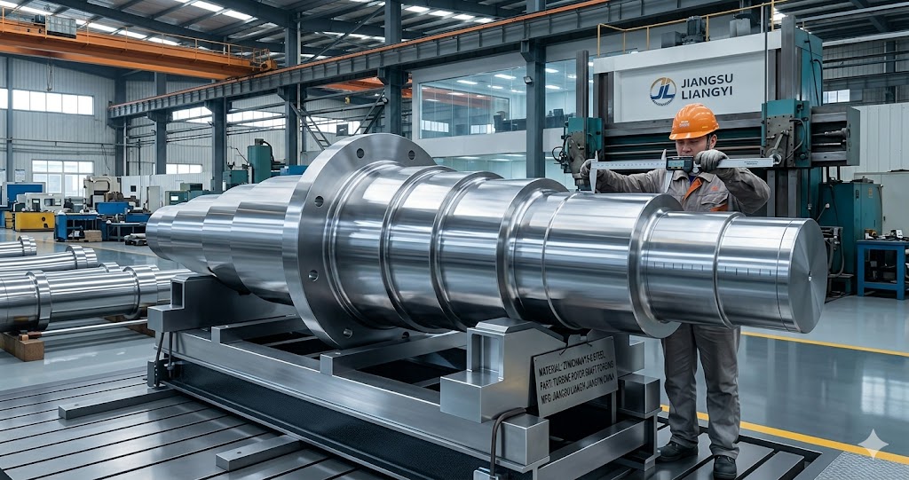
27NiCrMoV15-6 Forging Steel Parts | Jiangsu Liangyi Jiangyin China Factory
Jiangsu Liangyi Co., Limited is a professional 27NiCrMoV15-6 forging manufacturer and supplier based in Jiangyin, China — the world-renowned core industrial cluster of high-quality heavy open die forgings in East China. With over 25 years of specialized experience, we produce premium 27NiCrMoV15-6 (also designated as 27NiCrMoV15.6, 27NiCrMoV156) steel components manufactured to SEW 555:1984 and tested per ASTM A388, EN 10228-3, and other customer-specified international standards. Our products are exported to more than 50 countries, serving global industrial clients from Germany, the USA, India, Southeast Asia, and the Middle East. Get a free, no-obligation quotation for your 27NiCrMoV15-6 forging needs today!
What is 27NiCrMoV15-6 Creep Resisting Steel?
27NiCrMoV15-6 is a low-alloy, high-strength creep resisting steel grade specifically developed by the German Steel Institute (SEW) for large forgings used in turbine and generator production. The designation follows the DIN German naming convention: "27" indicates the nominal carbon content of 0.27%; "Ni15" indicates approximately 3.75% nickel (15 ÷ 4); and "CrMoV" identifies the secondary alloying elements, with "6" representing approximately 1.5% chromium (6 ÷ 4). The combination of nickel, chromium, molybdenum, and vanadium gives this grade its characteristic high-temperature strength and creep resistance.
Through alloying with 3.40–4.00% nickel, 1.20–1.80% chromium, 0.25–0.45% molybdenum and 0.05–0.15% vanadium, this engineered steel delivers a balanced property profile that sets it apart from conventional turbine-grade steels. Main performance advantages include exceptional high-temperature tensile strength, reliable creep resistance at service temperatures up to 550°C, sound low-temperature toughness down to −20°C, and outstanding thermal fatigue resistance under repeated cyclic thermal and mechanical loading. Elevated nickel content acts as the core differentiating element. It substantially enhances deep-section hardenability for heavy forgings, enables consistent martensitic transformation across full cross-sections exceeding 1,500 mm, and optimizes ductile‑to‑brittle transition behaviour when benchmarked against low-nickel alternative turbine steel grades.
Main Advantages of 27NiCrMoV15-6 Over Conventional Turbine Steels
- 30% higher creep rupture strength than standard carbon steels at 500 °C, enabling thinner-wall designs and weight reduction in turbine rotor assemblies
- Excellent resistance to stress corrosion cracking (SCC) in wet steam and high-sulfur oil environments
- Uniform mechanical properties throughout large cross-sections up to 2,000 mm in diameter — an important advantage over lower-nickel grades where core properties degrade in thick sections
- Good hardenability and machinability after quenching and tempering (Q&T), with surface hardness typically in the 270 – 320 HB range
- Cost-effective alternative to high-nickel superalloys for mid-temperature (450 – 550 °C) applications in combined-cycle and steam turbine systems
- Better resistance to temper embrittlement than 30CrMoNiV5-11 due to the higher nickel-to-chromium ratio and strictly controlled P and Sn impurity levels
27NiCrMoV15-6 Chemical Composition (SEW 555:1984 Standard)
The chemical composition of 27NiCrMoV15-6 is tightly controlled under SEW 555:1984 to ensure consistent hardenability and high-temperature performance across all forging sizes. We make our steel ingots at Jiangsu Liangyi in our own electric arc furnace (EAF), ladle furnace refining (LF), and vacuum degassing (VOD) facility. The levels of phosphorus and sulfur are usually much lower than the standard maximums.
| Element | Symbol | Min (%) | Max (%) | Role in Steel Performance |
|---|---|---|---|---|
| Carbon | C | 0.22 | 0.32 | Controls hardness and strength after Q&T; upper limit prevents excessive brittleness |
| Manganese | Mn | 0.15 | 0.40 | Deoxidizer; slightly improves hardenability; kept low to minimize temper embrittlement risk |
| Silicon | Si | — | 0.15 | Very low Si minimizes susceptibility to temper embrittlement in service |
| Phosphorus | P | — | 0.010 | Strictly limited; P segregates to grain boundaries and causes intergranular embrittlement |
| Sulfur | S | — | 0.007 | Low S ensures high impact toughness and transverse ductility; reduces MnS inclusions |
| Chromium | Cr | 1.20 | 1.80 | Improves hardenability, oxidation resistance, and high-temperature strength |
| Nickel | Ni | 3.40 | 4.00 | Key element: ensures deep hardening in thick sections; substantially raises low-temperature toughness; reduces DBTT |
| Molybdenum | Mo | 0.25 | 0.45 | Primary creep-resistance contributor; stabilizes M2C and MC carbides at high temperature; reduces temper embrittlement |
| Vanadium | V | 0.05 | 0.15 | Refines austenite grain size; forms stable VC and V(C,N) precipitates that pin dislocations and provide creep strength |
27NiCrMoV15-6 Mechanical Properties (Quenched & Tempered)
The mechanical property requirements below apply to the Q&T condition per SEW 555:1984. Test specimens are taken from the worst-case position (deepest point from the surface, transverse direction) to guarantee that the entire cross-section meets these minimum values.
| Property | Symbol | Min. Requirement | Typical Achieved* | Test Standard |
|---|---|---|---|---|
| Tensile Strength | Rm | ≥ 930 MPa | 960 – 1,020 MPa | ISO 6892-1 |
| 0.2% Proof Strength | Rp0.2 | ≥ 780 MPa | 810 – 880 MPa | ISO 6892-1 |
| Elongation at Fracture | A5 | ≥ 18.0% | 19 – 22% | ISO 6892-1 |
| Reduction of Area | Z | ≥ 45.0% | 50 – 62% | ISO 6892-1 |
| Charpy Impact (RT, avg / min) | KV | ≥ 40 J avg / ≥ 28 J min | 60 – 95 J | ISO 148-1 |
| Charpy Impact (−20 °C, by agreement) | KV | ≥ 27 J | 40 – 70 J | ISO 148-1 |
| Brinell Hardness (surface) | HB | 270 – 320 (typical range) | 280 – 310 HB | ISO 6506-1 |
*Typical achieved values represent our production track record on 500 – 1,500 mm diameter forgings. Actual values reported on the EN 10204 3.1 inspection certificate supplied with each delivery.
27NiCrMoV15-6 Physical & Thermal Properties vs. Temperature
The following physical and thermal properties are essential for engineering calculations including thermal stress analysis, turbine rotor dynamics simulation, and heat transfer modeling. Engineers are advised to use the temperature-dependent values from the table rather than single ambient-temperature figures in high-temperature design calculations, as properties such as elastic modulus and thermal expansion change significantly between 20 °C and 550 °C.
| Property | Unit | 20 °C | 200 °C | 400 °C | 500 °C | 550 °C |
|---|---|---|---|---|---|---|
| Density (ρ) | g/cm³ | 7.85 | 7.80 | 7.72 | 7.67 | 7.64 |
| Elastic Modulus (E) | GPa | 206 | 196 | 183 | 175 | 170 |
| Shear Modulus (G) | GPa | 80 | 76 | 71 | 68 | 66 |
| Poisson’s Ratio (ν) | — | 0.290 | 0.292 | 0.295 | 0.296 | 0.297 |
| Thermal Conductivity (λ) | W/(m·K) | 36.5 | 35.0 | 33.0 | 31.5 | 30.5 |
| Specific Heat Capacity (cp) | J/(kg·K) | 480 | 510 | 545 | 570 | 585 |
| Mean Thermal Expansion α (from 20 °C) | 10⁻⁶/K | — | 11.8 | 12.8 | 13.4 | 13.7 |
| Electrical Resistivity | μΩ·m | 0.25 | 0.36 | 0.52 | 0.62 | 0.68 |
27NiCrMoV15-6 High-Temperature Creep Rupture Strength Data
Creep rupture strength — the stress that causes fracture after a specified time at elevated temperature — is the single most important design property for turbine rotor shafts and steam valve components. The data below represents the stress to cause rupture in 100,000 hours (approximately 11.4 years of continuous operation) for 27NiCrMoV15-6 in the Q&T condition, derived from time-temperature parametric analysis of long-duration test data.
These figures are representative of forgings in the 300 – 800 mm effective diameter range. Engineers should apply a safety factor appropriate to their design code (typically 1.5× per EN 13480 or ASME B31.1) and note that creep strength is sensitive to section size: larger forgings with slower through-thickness cooling may exhibit 5 – 10% lower creep strength at the core compared to the values shown here.
| Temperature | Rupture in 10,000h (MPa) | Rupture in 100,000h (MPa) | 1% Creep in 100,000h (MPa) | Typical Application |
|---|---|---|---|---|
| 450 °C | ≥ 360 | ≥ 280 | ≥ 240 | LP turbine rotor shafts, valve bodies, high-pressure casings |
| 480 °C | ≥ 300 | ≥ 245 | ≥ 200 | IP turbine rotor shafts, compressor discs |
| 500 °C | ≥ 265 | ≥ 220 | ≥ 175 | HP/IP turbine rotor shafts — primary design temperature for this grade |
| 520 °C | ≥ 210 | ≥ 160 | ≥ 130 | Advanced HP rotors; approaching upper useful limit of grade |
| 550 °C | ≥ 145 | ≥ 100 | ≥ 80 | Limiting condition; consider X12CrMoWVNbN10-1-1 above this temperature |
Interpreting Creep Data: Guidance for Turbine Engineers
The 100,000-hour rupture stress of 220 MPa at 500 °C is the benchmark value cited most frequently in turbine procurement specifications. When comparing 27NiCrMoV15-6 against alternative grades, this number captures long-term structural reliability. Practically:
- At 450 – 500 °C: 27NiCrMoV15-6 is the preferred choice for HP and IP turbine rotor shafts in subcritical and supercritical steam plants, offering an excellent balance of creep strength, toughness, and deep hardenability
- At 500 – 520 °C: The grade remains serviceable but approaches its practical limit; thermal cycling duty cycles and the number of cold starts must be carefully evaluated in fatigue-creep interaction assessments
- Above 550 °C: 9 – 12% chromium martensitic steels (e.g., X12CrMoWVNbN10-1-1 or X10CrMoVNb9-1) are required; 27NiCrMoV15-6 should not be specified for primary structural duty above this temperature in new designs
27NiCrMoV15-6 International Equivalent Grades
Because 27NiCrMoV15-6 was developed specifically under the German SEW 555 standard for large turbine forgings, no other national standard has an identical equivalent. The grade’s combination of high nickel content (3.5 – 4.0%), controlled vanadium addition, and the ultra-low P/S requirements places it in a unique category. When procurement documents or engineering drawings reference this grade across different national standards, the following closest approximate equivalents are used in practice. Engineers must always verify actual composition and property requirements before substituting.
| Standard / Country | Designation / Grade | Key Composition Difference | Equivalence Level |
|---|---|---|---|
| SEW 555:1984 (Germany) — Primary | 27NiCrMoV15-6 | Reference grade | ✓ Exact |
| ASTM A470 (USA) | Grade D (Class 7) | Lower Ni (1.5 – 2.0%); A470 is a forging specification, not a composition specification — must confirm Ni content with supplier | ⚠ Approximate; lower Ni content |
| ASTM A291 (USA) | Grade 6 | Lower Ni (~1.8 – 2.2%); slightly different Cr-Mo balance; no vanadium requirement | ⚠ Approximate; lower creep performance |
| GOST 25054 (Russia) | 38KhN3MFA | Higher C (0.33 – 0.40%); similar Ni (3.0 – 3.5%); higher Mo (0.35 – 0.45%); V 0.10 – 0.18% | ⚠ Close but higher carbon; weldability and toughness may differ |
| JIS G3203 (Japan) | SFVQ2A | Ni 3.00 – 4.00%; Cr 1.00 – 2.00%; Mo 0.25 – 0.50%; V 0.05 – 0.15% — composition very close; property requirements similar | ✓ Close — widely accepted as equivalent in Japanese procurement |
| BS (United Kingdom) | No direct equivalent | BS 970 and BS EN 10083 do not cover this high-Ni turbine forging grade; specify by SEW 555 designation | ✗ No BS equivalent |
| GB/T (China) | No direct standard equivalent | Chinese national standards do not include this specific composition for turbine forgings; testing can be arranged at a CNAS-accredited third-party laboratory upon request | ✗ Specify SEW 555 directly |
| NF A35-573 (France) | 25NiCrMo14 (approximate) | Slightly lower C range; similar Ni-Cr-Mo; no standard vanadium addition — V significantly affects long-term creep performance | ⚠ Partial — V content difference affects creep strength |
Multi-Grade Choice Matrix: 27NiCrMoV15-6 vs Competing Turbine Steel Grades
Choosing the right turbine forging steel needs balancing creep strength, low-temperature toughness, hardenability (important in large cross-sections), machinability, weldability, and cost. The matrix below compares 27NiCrMoV15-6 against the four most commonly considered alternatives across the full range from general-purpose grades to advanced high-chromium steels. The highlighted column is 27NiCrMoV15-6.
| Property / Criterion | 26NiCrMoV14-5 (SEW 555) | ★ 27NiCrMoV15-6 (SEW 555) | 30CrMoNiV5-11 (SEW 555) | 34CrNiMo6 (EN 10083-3) | X12CrMoWVNbN10-1-1 (EN 10269) |
|---|---|---|---|---|---|
| Ni Content (%) | 3.25 – 3.75 | 3.40 – 4.00 | 0.80 – 1.20 | 1.30 – 1.70 | ≤ 0.40 |
| Cr Content (%) | 1.00 – 1.50 | 1.20 – 1.80 | 2.50 – 3.00 | 1.30 – 1.70 | 9.50 – 10.50 |
| Max. Service Temp. (°C) | 530 | 550 | 540 | 480 | 620 |
| 100,000h Creep Rupture (500°C, MPa) | ~200 | ≥ 220 | ≥ 180 | ~130 | ≥ 180 |
| Min. Tensile Strength Rm (MPa) | 880 | 930 | 900 | 1,000 | 760 |
| KV at −20°C (typical, J) | 55 – 80 | 40 – 70 | 25 – 40 | 30 – 50 | 40 – 60 |
| Deep Hardenability (thick sections) | Excellent | Excellent | Good | Moderate | Good |
| Max. Practical Section (mm dia.) | Up to 2,000 | Up to 2,000 | Up to 1,500 | Up to 800 | Up to 1,200 |
| Relative Material Cost | Medium-High | Medium-High | Medium | Medium | High |
| Typical Applications | LP/IP rotors, large discs | HP/IP rotors, valve spindles, rings | HP rotors, pressure casings | General shafts, gear blanks | Advanced USC HP rotors |
| Weldability | Moderate (preheat) | Moderate (preheat + PWHT) | Moderate (preheat + PWHT) | Good (lower preheat) | Difficult (strict PWHT) |
When to Choose 27NiCrMoV15-6: A Practical Decision Guide
- Choose 27NiCrMoV15-6 when your component operates continuously in the 450 – 550 °C range, requires uniform properties throughout a cross-section exceeding 500 mm, or demands excellent low-temperature toughness (e.g., cold-climate installation or frequent startup-shutdown cycling)
- Choose 26NiCrMoV14-5 when the maximum section size exceeds 1,800 mm and the slightly lower creep strength at core positions is acceptable per your finite element analysis
- Choose 30CrMoNiV5-11 when operating temperature exceeds 540 °C but budget constraints rule out 9 – 12%Cr steels, and the smaller cross-section (≤ 1,200 mm) allows adequate through-hardening
- Choose 34CrNiMo6 for general-purpose mechanical applications below 480 °C where creep is not the primary design driver and cost is a priority
- Choose X12CrMoWVNbN10-1-1 when your design steam temperature exceeds 565 °C (ultra-supercritical plant) and the premium price is justified by the thermodynamic efficiency gain
27NiCrMoV15-6 Welding Guidelines & Parameters
Welding 27NiCrMoV15-6 demands rigorous procedure qualification and strict parameter control due to the steel’s high hardenability and susceptibility to hydrogen-induced cold cracking (HICC) in the heat-affected zone (HAZ). The parameters below are based on our production experience welding this grade for turbine component repair, shaft coupling attachment, and end-cap welding on hollow forgings. All procedures must be qualified per ISO 15614-1 (or ASME Section IX) before production welding commences.
| Parameter | Requirement | Notes |
|---|---|---|
| Preheat Temperature (Tp) | 150 – 200 °C (sections > 25 mm) 100 – 150 °C (sections ≤ 25 mm) | Measure at minimum 75 mm from weld centerline; maintain throughout entire welding operation |
| Maximum Interpass Temperature | ≤ 300 °C | Exceeding 300 °C risks softening of the HAZ tempered martensite and loss of toughness |
| Post-Weld Heat Treatment (PWHT) | 580 – 630 °C Hold: min 2h per 100 mm thickness, min 2h total | Mandatory for all structural joints; cool at ≤ 50 °C/h to 300 °C then free-cool to ambient |
| PWHT Heating Rate | ≤ 80 °C/h above 300 °C | Controlled heating essential to prevent thermal shock in heavy sections (> 200 mm) |
| Hydrogen Control (Hd) | ≤ 5 ml H₂/100 g deposited weld metal | Use only low-hydrogen consumables; bake electrodes per manufacturer specification before use |
| Filler Metal — SMAW | AWS A5.5: E9018-G or E9018-D1 | Matching strength; H4 or H2R low-hydrogen coating designation preferred; E10018-G acceptable for higher-strength joints |
| Filler Metal — GMAW / GTAW | AWS A5.28: ER90S-G | GTAW for root passes; GMAW for fill and cap passes on automated welding stations |
| Filler Metal — SAW | AWS A5.23: F9P2-EB3-B3 or equivalent | Use with basic-type low-hydrogen flux; control heat input per WPS to avoid HAZ coarsening |
| Heat Input Control | 0.8 – 2.5 kJ/mm (process-dependent) | Higher heat input (> 2.5 kJ/mm) risks HAZ grain coarsening; lower (< 0.8 kJ/mm) risks lack of fusion |
| NDT After PWHT | 100% UT (ASTM A388) + 100% MT (ASTM E709) | All indications exceeding the reference level must be evaluated and formally dispositioned |
| Hydrogen Bake-Out (delayed PWHT) | 200 – 250 °C × 4h min, immediately after welding | Required if PWHT is delayed more than 4h; prevents HICC during storage or transport |
Precision Heat Treatment Parameters for 27NiCrMoV15-6
To achieve optimal mechanical properties, all 27NiCrMoV15-6 forgings at Jiangsu Liangyi undergo a strictly computer-controlled quenching and tempering (Q&T) process. Each furnace zone is independently controlled with calibrated type K or type N thermocouples, and complete real-time temperature records are retained as part of the EN 10204 3.1 inspection documentation package. Our heat treatment capability covers single pieces up to 30 tons and 6,000 mm in length in our car-bottom furnaces.
- Stress Relief Anneal (after rough forging, if required): Heat to 550 – 600 °C and hold for 1 – 3 hours per 100 mm to relieve residual stresses and improve machinability before finish machining or initial inspection
- Preheating: Slowly heat to 600 – 650 °C at ≤ 60 °C/hour and hold for 1 – 2 hours per 100 mm of maximum cross-section thickness to eliminate temperature differentials in large sections that could cause thermal cracking
- Austenitizing: Heat to 860 – 900 °C at ≤ 80 °C/hour and hold for 1.5 – 3 hours per 100 mm of thickness to ensure complete, uniform austenite formation throughout the entire forging cross-section
- Quenching: Transfer to quench tank within 30 seconds of furnace exit; quench in oil (preferred) or polymer quenchant (PAG concentration adjusted for section size) to achieve a fully martensitic microstructure; minimum quench rate to 300 °C must exceed 10 °C/minute at the core
- Intermediate Temper (heavy sections > 800 mm dia.): Apply an intermediate temper at 550 – 580 °C for 2h per 100 mm before final tempering to reduce hydrogen content and relieve quench stresses, improving final toughness
- Final Tempering: Heat to 580 – 650 °C and hold for 2 – 4 hours per 100 mm of thickness, followed by controlled air cooling at ≤ 50 °C/hour to 300 °C, then free air cooling to ambient — getting the target balance of strength, toughness, and creep resistance
Complete Range of 27NiCrMoV15-6 Forged Products & Size Specifications
At Jiangsu Liangyi, we manufacture a full spectrum of custom 27NiCrMoV15-6 forged parts to your detailed drawings and technical specifications. Our advanced forging and inspection equipment enables us to produce components across the full size range below. Components outside these ranges may be feasible — contact our engineering team for a feasibility review.
Forged Bars — Size Specifications
| Bar Type | Cross-Section Range | Max Length | Max Single Weight | Typical As-Forged Tolerance |
|---|---|---|---|---|
| Round Bar | Ø50 – Ø2,000 mm | 12,000 mm | ~30 tons | +4 / −0 mm on diameter |
| Square Bar | 50×50 – 800×800 mm | 8,000 mm | ~20 tons | +5 / −0 mm on width |
| Flat Bar / Slab | Thickness 20 – 500 mm; Width 50 – 2,000 mm | 8,000 mm | ~25 tons | +5 / −0 mm on thickness |
| Rectangular Bar | 50×80 – 700×1,200 mm | 8,000 mm | ~20 tons | +5 / −0 mm |
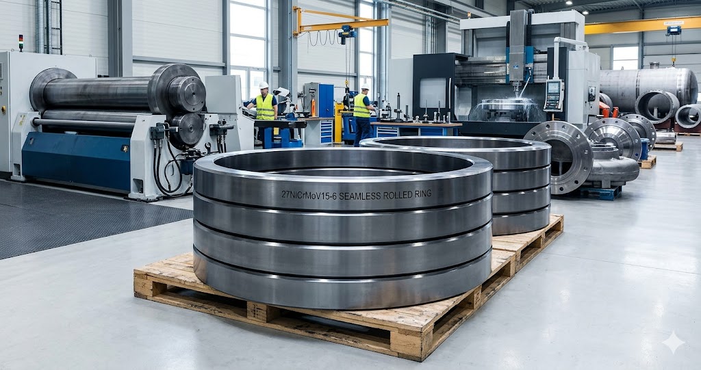
Seamless Rolled Rings — Size Specifications
| Parameter | Minimum | Maximum | Notes |
|---|---|---|---|
| Outer Diameter (OD) | 300 mm | 6,000 mm | OD tolerance: ±3 mm for OD ≤ 1,000 mm; ±5 mm for OD > 1,000 mm |
| Inner Diameter (ID) | 150 mm | 5,600 mm | Minimum wall thickness ratio: OD/wall ≤ 12:1 without special tooling setup |
| Ring Height | 50 mm | 3,000 mm | Height-to-wall-thickness ratio ≤ 8:1 for standard rolling; consult for taller rings |
| Wall Thickness | 30 mm | 1,000 mm | Walls > 600 mm require metallurgical review for guaranteed core Q&T properties |
| Unit Weight | 5 kg | 30,000 kg | Rings > 20 tons require engineering review and extended lead time (14 – 16 weeks) |
Turbine Rotor Shafts — Size Specifications
| Parameter | Minimum | Maximum | Notes |
|---|---|---|---|
| Overall Length | 500 mm | 15,000 mm | Shafts > 10 m produced by upset forging + drawing on extended-hearth car-bottom furnace |
| Main Body Diameter | 100 mm | 2,000 mm | Rough-forged tolerance ±0.5%; CNC finish tolerance ±0.02 mm available |
| Single-Piece Weight | 0.05 tons | 30 tons | 30-ton limit set by ingot capacity (EAF + controlled 4-strand casting) |
| Max Step Ratio (max/min dia.) | Up to 4:1 in a single forging | Higher ratios may require semi-finish forging + CNC rough machining as intermediate step | |
| Straightness (rough-machined) | ≤ 0.5 mm per 1,000 mm length | Tighter requirements (< 0.2 mm/m) require stress-relief + correction straightening | |
| Bearing Journal Finish (CNC) | ±0.02 mm diameter; Ra ≤ 1.6 μm | Achieved on our 5-axis CNC center with Renishaw in-process gauging | |
Discs, Blocks & Other Forging Shapes
| Product Type | Size Range | Max Weight |
|---|---|---|
| Discs / Turbine Wheel Blanks | Ø200 – Ø3,000 mm; Thickness 50 – 1,500 mm | 20 tons |
| Blocks / Rectangular Forgings | L 200 – 6,000 mm × W 100 – 2,000 mm × H 50 – 1,000 mm | 25 tons |
| Flanged Shafts / Stepped Discs | Flange OD up to Ø3,000 mm; Shaft body Ø up to Ø800 mm | 20 tons |
| Hollow Bars / Heavy-Wall Cylinders | OD Ø200 – Ø3,000 mm; Wall ≥ 30 mm; Length up to 6,000 mm | 20 tons |
| Valve Spindles & Stems | Ø20 – Ø500 mm body; L up to 4,000 mm | 3 tons |
| High-Strength Studs & Fasteners | M20 – M160; Length up to 2,000 mm | 0.05 tons per piece |
27NiCrMoV15-6 Industrial Applications & Proven Global Success Cases
27NiCrMoV15-6 steel is primarily used in power generation, oil & gas, marine, and heavy industrial sectors. Our forged components have been successfully supplied for projects worldwide, including:
- Southeast Asian Thermal Power Plants: Multiple sets of 27NiCrMoV15-6 steam turbine rotor shafts for continuous high-temperature, high-pressure service, with ongoing repeat orders reflecting reliable field performance
- European Combined-Cycle Plants: Precision gas compressor turbine blades and discs machined to tight dimensional tolerances per customer drawings
- Middle East Oil & Gas Projects: 27NiCrMoV15-6 valve spindles and seat rings for high-pressure steam turbine systems, supplied with EN 10204 3.1 inspection certificates
- Industrial Marine Applications: Turbine shaft components for ship propulsion systems, inspected to buyer-specified UT and MT acceptance levels
- High-Strength Fastener Programs: Custom studs and bolts for pressure vessel and turbine casing assemblies, heat-treated and 100% hardness-tested before dispatch
Ready to discuss your 27NiCrMoV15-6 forging project? Contact our sales team for a customized solution!
Advanced Manufacturing Process for 27NiCrMoV15-6 Forgings
Our state-of-the-art manufacturing facilities enable us to produce 27NiCrMoV15-6 forgings with consistent, high-quality results. Our complete in-house process includes:
- In-House Steel Melting: Our own electric arc furnace (EAF) + ladle refining furnace (LF) + vacuum degassing (VOD) process, achieving ultra-low impurity levels (P ≤ 0.007%, S ≤ 0.004%) and full melt traceability from heat number to finished forging
- Controlled Ingot Casting: Solidification in protective atmosphere to minimize macro-segregation, porosity, and inclusions
- Multi-Stage Open Die Forging: 2,000 – 6,300-ton hydraulic presses with a minimum 3:1 forging ratio to refine grain structure and close internal voids
- Precision Heat Treatment: Computer-controlled Q&T with independently regulated furnace zones, calibrated thermocouples, and full temperature traceability records
- CNC Machining: High-precision 5-axis CNC machining to dimensional tolerances as tight as ±0.02 mm
- Rigorous Quality Inspection: Ultrasonic testing, magnetic particle testing, hardness survey, chemical analysis, and mechanical testing carried out by our in-house qualified NDT and QC team before every dispatch
Industry Standards & Compliance
All our 27NiCrMoV15-6 forgings are manufactured and tested in accordance with the following international standards and customer-specified requirements:
- SEW 555:1984 — Steels for larger forgings for turbine and generator components (material specification)
- EN 10228-3 — Non-destructive testing of steel forgings: ultrasonic testing (UT inspection standard)
- ASTM A388 — Standard practice for ultrasonic examination of steel forgings
- ASTM E709 — Standard guide for magnetic particle testing
- ISO 9001:2015 — Quality management systems (Jiangsu Liangyi is ISO 9001:2015 certified)
- EN 10204 — Metallic products: types of inspection documents. EN 10204 Type 3.1 inspection certificate issued as standard with every delivery. EN 10204 Type 3.2 (countersigned by buyer-nominated independent TPI body) available upon arrangement.
Comprehensive Quality Assurance System
Quality is the foundation of our business at Jiangsu Liangyi. Every 27NiCrMoV15-6 forged part undergoes strict quality control at every stage of the production process. We provide an EN 10204 Type 3.1 inspection certificate as standard with every delivery, which includes:
- Complete identification and order information
- Material designation and heat number
- Full chemical analysis including trace elements (As, Sn, Sb, Cu, N)
- Ingot weight, L/D ratio, and forging reduction data
- Detailed heat treatment records (temperature, time, cooling rate, and all reheat treatments)
- Mechanical test results with specimen locations
- Residual stress measurement results (if required by order)
- Ultrasonic and magnetic particle inspection reports
- Final dimensional inspection data sheet
EN 10204 Type 3.2 certification (countersigned by an independent inspection body such as SGS, BV, TÜV Rheinland, DNV, or ABS) is available upon request — please specify at time of order.
27NiCrMoV15-6 Fatigue & Fracture Properties
Startup-shutdown sequences, speed transients, and rotating bending loads put cyclic stress on the turbine rotor shafts and compressor discs. It is just as important to know how 27NiCrMoV15-6 behaves when it is tired and broken as it is to know how it behaves when it is still. The data below covers fatigue endurance, fracture toughness, and crack propagation parameters — all of which must be considered in fail-safe damage-tolerant design per API 579-1 / ASME FFS-1 or EN 13445-8.
| Property | Symbol | Temperature | Representative Value | Test / Reference Standard |
|---|---|---|---|---|
| Fatigue Endurance Limit (rotating bending, unnotched, R=−1) | σ₁ | 20 °C | ~375 – 400 MPa | ISO 1099 / ASTM E466 |
| Fatigue Endurance Limit (rotating bending, unnotched, R=−1) | σ₁ | 500 °C | ~250 – 275 MPa | ISO 1099 / ASTM E466 |
| Fatigue Strength Ratio (σ₁ / Rm) | — | 20 °C | ~0.40 | Derived |
| Notch Sensitivity Factor (Kt=2.5) | q | 20 °C | 0.75 – 0.85 | ASTM E1049 |
| Fatigue Notch Factor (Kt=2.5, Kf) | Kf | 20 °C | 1.90 – 2.10 | Derived (Kf = 1 + q(Kt−1)) |
| Fracture Toughness (plane strain, KIC) | KIC | 20 °C | 100 – 135 MPa·m½ | ISO 12135 / ASTM E399 |
| Fracture Toughness (KIC) | KIC | 300 °C | 120 – 150 MPa·m½ | ISO 12135 |
| Critical Crack Size (at Rp0.2=800 MPa) | ac | 20 °C | ~5 – 9 mm (semi-elliptical surface crack) | Derived from KIC / π / σ² formula |
| Threshold Stress Intensity Range (ΔKth) | ΔKth | 20 °C | ~8 – 11 MPa·m½ | ASTM E647 |
| Paris Law Exponent | m | 20 °C | ~3.0 – 3.4 | ASTM E647 |
| Paris Law Coefficient | C | 20 °C | ~3 × 10⁻¹² (MPa·m½, m/cycle) | ASTM E647 |
Practical Fatigue Design Guidance for 27NiCrMoV15-6 Components
The high-nickel content of 27NiCrMoV15-6 confers two specific advantages in fatigue-critical applications compared with lower-nickel turbine steels. First, it substantially reduces the ductile-to-brittle transition temperature (DBTT), shifting the fracture mode transition to below −40 °C in well-heat-treated material — this means the steel maintains high fracture toughness even during cold startup conditions where thermal shock could cause brittle fracture in less tough grades. Second, the high KIC values (100 – 135 MPa·m½) result in a generous critical crack size (typically 5 – 9 mm for surface semi-elliptical cracks at working stress), providing substantial margin for in-service inspection programs to detect defects before they reach critical size.
Temper Embrittlement Assessment: J-Factor, X-Factor & Step Cooling Testing
Temper embrittlement is the most critical metallurgical degradation mechanism in Ni-Cr-Mo-V turbine steels in long-term service at 350 – 550 °C. It occurs when tramp elements (primarily phosphorus, antimony, tin, and arsenic) segregate to prior austenite grain boundaries during slow cooling or extended service at these temperatures, raising the ductile-to-brittle transition temperature (DBTT) without any detectable change in room-temperature strength. Because turbine rotor shafts remain in service for 20 – 40 years, temper embrittlement resistance is a mandatory qualification criterion for this grade. Two quantitative indices are used globally:
The Bruscato X-Factor (Temper Embrittlement Susceptibility Index)
The Bruscato X-factor quantifies the combined effect of the four most potent embrittling tramp elements on grain-boundary segregation kinetics:
(where P, Sb, Sn, As are expressed in ppm by weight)
Industry limit for 27NiCrMoV15-6 turbine forgings: X ≤ 15 (VGB requirement); X ≤ 20 (typical buyer spec)
Jiangsu Liangyi typical achieved value: X = 6 – 10 (P ≤ 70 ppm, Sn ≤ 15 ppm, Sb ≤ 5 ppm, As ≤ 20 ppm)
The Watanabe-Iwasaki J-Factor (Grain-Boundary Segregation Risk)
The J-factor also accounts for silicon and manganese, which act as co-segregants that enhance the grain-boundary accumulation of phosphorus and tin. It is defined as:
(where Si, Mn, P, Sn are expressed in wt%)
Premium quality limit: J ≤ 100 (most buyer specs); J ≤ 60 (nuclear and critical power applications)
Jiangsu Liangyi typical achieved value: J = 25 – 45 (based on Si ≤ 0.10%, Mn ≤ 0.30%, P ≤ 0.007%, Sn ≤ 0.001%)
| Index | Formula | Critical Threshold | Jiangsu Liangyi Typical | Significance |
|---|---|---|---|---|
| Bruscato X-Factor | (10P+5Sb+4Sn+As)/100 | ≤ 15 (VGB); ≤ 20 (typical) | 6 – 10 ✅ | Controls grain-boundary embrittlement in service at 350 – 550 °C |
| J-Factor | (Si+Mn)×(P+Sn)×10⁴ | ≤ 100 (standard); ≤ 60 (nuclear) | 25 – 45 ✅ | Combined segregation risk from Si, Mn, P, Sn interactions |
| P + Sn max (ppm) | P + Sn | ≤ 120 ppm (some buyer specs) | ≤ 85 ppm ✅ | Simple limit on the two most active grain-boundary segregants |
| DBTT Shift after Step Cooling | ΔDBTT | ≤ +25 °C (premium); ≤ +40 °C (standard) | +12 to +20 °C ✅ | Measured after accelerated step-cooling simulation per ASTM A469 |
Step Cooling Test Capability
For clients requiring quantitative evidence of temper embrittlement resistance beyond the chemical index approach, Jiangsu Liangyi offers step cooling simulation testing on production or separately forged test blocks from the same heat. The step cooling cycle (per SEP 1923 or equivalent buyer specification) thermally simulates 20 – 40 years of service at 480 °C in approximately 10 days of controlled furnace cycling. Pre- and post-step-cooling Charpy transition curves are generated and the DBTT shift (ΔDBTT) is reported in the EN 10204 3.1 inspection document. Our consistently low X-Factor (6 – 10) and J-Factor (25 – 45) translate into step-cooling DBTT shifts well below 25 °C — meeting the most demanding premium turbine forging specifications.
Carbon Equivalent & Weldability Assessment for 27NiCrMoV15-6
The carbon equivalent (CE) quantifies the combined hardenability effect of all alloying elements and is the primary index used to assess cold cracking risk during welding. Because 27NiCrMoV15-6 contains high nickel (3.7%), significant chromium (1.5%), and molybdenum (0.35%) in addition to 0.27% carbon, its CE values are substantially higher than those of structural steels — explaining why this grade demands the strict preheat and PWHT requirements described in our welding section.
Three commonly used CE formulae are shown below, calculated for a representative heat analysis (C=0.27%, Mn=0.30%, Si=0.10%, P=0.007%, Cr=1.50%, Ni=3.70%, Mo=0.35%, V=0.10%, Cu=0%):
| CE Formula | Expression | Calculated Value | Risk Classification | Applicable Standard |
|---|---|---|---|---|
| IIW Carbon Equivalent (CEIIW) | C + Mn/6 + (Cr+Mo+V)/5 + (Ni+Cu)/15 | 0.27 + 0.05 + 0.39 + 0.247 = 0.96 | Very High ⚠ — strict preheat mandatory | ISO/TR 17671-2 |
| Ito-Bessyo Pcm (cold cracking) | C + Si/30 + Mn/20 + Cu/20 + Ni/60 + Cr/20 + Mo/15 + V/10 + 5B | 0.27 + 0.003 + 0.015 + 0.062 + 0.075 + 0.023 + 0.010 = 0.458 | High — preheat 150 – 200 °C required | AWS D1.1 |
| CET (European, EN 1011-2) | C + (Mn+Mo)/10 + (Cr+Cu)/20 + Ni/40 | 0.27 + 0.065 + 0.075 + 0.093 = 0.503 | Very High ⚠ — preheating essential | EN 1011-2 |
Graville Diagram Position
Plotting 27NiCrMoV15-6 on the Graville weldability diagram (CE vs. carbon content) places this grade firmly in Zone III — the "difficult to weld" region where both the carbon content and the hardenability are high, making hydrogen-induced cracking (HIC) a serious risk without proper preheat, low-hydrogen consumables, and mandatory PWHT. This is consistent with the welding parameters specified earlier (preheat 150 – 200 °C, PWHT 580 – 630 °C) and highlights why all welding procedures must be rigorously qualified before production welding. Zone III steels are not inherently impossible to weld — they simply require metallurgically sound procedures, and 27NiCrMoV15-6 has an excellent field service record when these procedures are followed.
27NiCrMoV15-6 Machinability & CNC Cutting Parameters
With a hardness of 280 – 310 HB in the Q&T condition, 27NiCrMoV15-6 is a moderately challenging material to machine. Its high nickel content increases work-hardening tendency compared to lower-alloy turbine steels, and the stable carbide precipitates (principally Mo₂C, V₄C₃, and Cr₃C₂) are significantly harder than the ferritic matrix. However, the material is not unusually difficult by the standards of industrial alloy steels: with the correct cutting parameters and tooling, 27NiCrMoV15-6 can be machined to tight tolerances (±0.02 mm) and fine surface finishes (Ra ≤ 1.6 μm) routinely. The table below provides our in-house production machining parameters as a guide to customers performing their own final machining:
| Operation | Cutting Speed (m/min) | Feed Rate | Depth of Cut | Tooling Recommendation |
|---|---|---|---|---|
| Rough Turning | 80 – 120 | 0.25 – 0.40 mm/rev | 3 – 8 mm | ISO P30 – P40 coated carbide (TiAlN); CNMG/SNMG insert geometry; 75 ° lead angle preferred |
| Finish Turning | 120 – 180 | 0.05 – 0.12 mm/rev | 0.2 – 0.5 mm | ISO P10 – P20 coated carbide (TiAlN); wiper insert geometry; sharp cutting edge; large nose radius (0.8 – 1.6 mm) |
| Rough Face Milling | 60 – 100 | 0.10 – 0.18 mm/tooth | 2 – 5 mm axial | ISO P25 – P40 coated carbide; 45 ° lead-angle face mill cutter; minimize radial engagement to 70% |
| Finish Face Milling | 100 – 150 | 0.04 – 0.07 mm/tooth | 0.3 – 1.0 mm axial | P10 – P15 CVD/PVD coated carbide; wiper insert; positive rake geometry; climb milling preferred |
| Drilling (solid carbide) | 25 – 45 | 0.10 – 0.20 mm/rev | Full diameter | TiAlN-coated carbide drill; through-coolant (70 bar) for holes deeper than 3×dia.; peck drilling for deep holes |
| Boring (fine bore) | 80 – 130 | 0.05 – 0.10 mm/rev | 0.1 – 0.4 mm | CBN or fine-grain carbide; single-point boring bar; dampened boring bar for L/D > 5; flood coolant essential |
| Cylindrical Grinding (journals) | 25 – 35 m/s (wheel) | 0.010 – 0.020 mm/pass (infeed) | — | 60-mesh Al₂O₃, vitrified bond (Norton 60I8VBE or equivalent); dress frequently; flood coolant to prevent thermal damage; Ra target ≤ 0.8 μm |
| Thread Milling (studs, fasteners) | 40 – 70 | 0.06 – 0.10 mm/tooth | Per thread pitch | Solid carbide thread mill; TiAlN coating; helical interpolation; flood or mist coolant |
Key Machinability Tips for 27NiCrMoV15-6
- Avoid work-hardening: Never make zero-feed dry "rubbing" passes; always maintain positive feed to ensure the cutting edge engages fresh material below the work-hardened layer from the previous pass
- Coolant strategy: Use water-soluble coolant (5 – 8% concentration) for all wet turning and milling operations. Dry machining is possible with coated carbide for roughing but significantly shortens tool life. For grinding, use ample flood coolant (≥ 100 L/min) to prevent surface burning and the formation of untempered martensite which would cause premature bearing failure
- Thermal damage detection: After bearing journal grinding, nital etch inspection (per ASTM B487) should be performed to verify the absence of grinding burn or rehardening zones. We recommend specifying nital etch as part of the acceptance criteria for all finish-ground bearing surfaces.
- Pre-machining stress relief: For tight-tolerance finish machining (±0.02 mm or finer), always perform a low-temperature stress relief (550 – 580 °C for 2 h) between rough and finish machining operations to relax residual stresses introduced by rough turning. Skip this step and dimensional drift during finish machining will exceed tolerances
NDT Acceptance Criteria & Inspection Details for 27NiCrMoV15-6 Forgings
Non-destructive testing (NDT) is performed on every 27NiCrMoV15-6 forging we produce as part of our standard quality assurance, not as an optional add-on. Our NDT capability includes ultrasonic testing (UT), magnetic particle testing (MT), liquid penetrant testing (PT), hardness testing, and visual inspection (VT). The acceptance criteria below represent our standard production requirements; buyers may specify more stringent levels by reference to a specific acceptance class in the standards listed.
| Test Method | Governing Standard | Standard Acceptance Level | Premium Acceptance Level | Scan Coverage |
|---|---|---|---|---|
| Ultrasonic Testing (UT) | EN 10228-3 / ASTM A388 | Quality Level 3 (QL3): max allowable indication = FBH 3mm equiv. at DAC −6 dB | Quality Level 4 (QL4): FBH 2mm; cleanliness level per SEP 1921 Class C/D | 100% volume scan: axial, circumferential, and radial directions for shafts; axial and radial for rings and discs |
| Magnetic Particle Testing (MT) | EN 10228-1 / ASTM E709 | Acceptance Level 2: no linear indications > 5 mm; no rounded indications > 8 mm in any 150×150 area | Acceptance Level 1: no linear indications > 3 mm; no rounded indications > 5 mm | 100% accessible external surfaces after rough machining; keyways, bores, and fillets receive additional focused MT scans |
| Liquid Penetrant Testing (PT) | EN 571-1 / ASTM E165 | Method C (non-aqueous wet developer): no indications > 3 mm linear; no clusters with > 3 indications in 100×100 area | No indications > 1.5 mm; used for finished bearing journals and precision surfaces | Finished bore surfaces, seal grooves, and areas inaccessible to MT; typically Method C with fluorescent penetrant |
| Hardness Testing (Brinell) | ISO 6506-1 / ASTM E10 | 270 – 320 HB (surface); hardness variation ≤ 30 HB between any two locations on the same piece | 280 – 310 HB; variation ≤ 20 HB | Minimum 4 surface locations (top, bottom, and 2 sides) per forging; end faces for long bars; additional checks on steps and flanges |
| Visual Inspection (VT) | EN 10163 Class A / ASTM A788 | No laps, seams, cracks, or sharp notches; surface scale from heat treatment acceptable if removable; grinding marks ≤ 0.5 mm deep permissible if blended | Class A1: all surfaces fully descaled; no grinding marks; all transitions blended to R ≥ 3 mm | 100% external surface on all forgings before dispatch; internal bores inspected by borescope if bore dia. ≥ 80 mm |
UT Reference Block Configuration (ASTM A388 / EN 10228-3 Comparison)
For shafts and round bars, our UT is performed using both longitudinal (compression) and shear wave probes, with reference calibration on a block machined from the same or equivalent 27NiCrMoV15-6 material at similar hardness. The calibration reflectors are:
- Flat-bottom holes (FBH): 2 mm and 3 mm diameter at depths of T/4, T/2, and 3T/4 (where T = component thickness or radius), per EN 10228-3 QL3/QL4
- Side-drilled holes (SDH): 1.5 mm diameter at T/4 and T/2 depth, per ASTM A388 Method 1 — used for longitudinal defect scanning on long shafts
- Back-wall echo technique: Used for attenuation characterization; forgings with back-wall signal loss > 6 dB compared to reference block are rejected or subjected to supplementary angle-probe scanning to locate the absorbing zone
27NiCrMoV15-6 Procurement Checklist & RFQ Guide
To ensure our quotation exactly matches your technical and commercial requirements, please include the following parameters in your request for quotation (RFQ). Incomplete RFQs are the most common cause of delivery delays — not manufacturing time. The table below serves as a procurement checklist for engineering teams issuing purchase orders for 27NiCrMoV15-6 forgings. Items marked ★ are mandatory; items marked ○ are recommended for quality-critical applications.
| # | Parameter | Recommended Specification Language | Priority |
|---|---|---|---|
| 1 | Grade & Standard | "27NiCrMoV15-6 per SEW 555:1984, heat analysis" — always specify the standard, not just the grade name | ★ |
| 2 | Product Form & Dimensions | Attach dimensioned drawing (preferred) or specify: form / OD or cross-section / length / wall thickness (if hollow) | ★ |
| 3 | Heat Treatment Condition | "Quenched and Tempered (Q+T)" — specify target hardness range if different from standard 270 – 320 HB | ★ |
| 4 | Mechanical Property Requirements | List each property with minimum value and test specimen orientation (Longitudinal / Transverse) and location (surface / T/4 / T/2 depth) | ★ |
| 5 | Impact Test Requirements | Specify test temperature (RT or −20 °C), specimen orientation (T), minimum average KV (J), and minimum single value KV (J) | ★ |
| 6 | Chemical Composition Restrictions | If stricter than SEW 555, specify P ≤ [x] ppm, S ≤ [x] ppm, and/or trace elements As, Sn, Sb maxima | ○ |
| 7 | Temper Embrittlement Indices | "J-Factor ≤ [XX]; Bruscato X-Factor ≤ [XX]" — required for critical turbine rotors and nuclear applications | ○ |
| 8 | Creep Requirements | Specify creep test temperature, stress, and minimum test duration if creep properties are required beyond standard SEW 555 | ○ |
| 9 | NDT Requirements | Reference standard (EN 10228-3 or ASTM A388) + acceptance level/class (QL3, QL4, or custom); specify if MT is also required | ★ |
| 10 | Certification Required | "EN 10204 Type 3.1" (internal TPI only) or "Type 3.2" (buyer or independent TPI witness required) | ★ |
| 11 | Third-Party Inspection (TPI) | Specify: Yes / No; which agency (SGS, BV, TÜV Rheinland, DNV, ABS, or client-nominated inspector) | ○ |
| 12 | Surface Condition | "As-forged" / "Rough-machined (peeled)" to +[X]mm on diameter / "Finish-machined per drawing" | ★ |
| 13 | Quantity & Delivery Schedule | Total weight (kg or ton) or number of pieces; required-by date; partial delivery acceptable: Yes / No | ★ |
| 14 | Shipping Terms & Destination Port | Incoterm (FOB Shanghai / CIF / EXW); destination port; import restrictions or documentation requirements | ★ |
| 15 | Marking & Identification | Specify heat number stamp location; color coding (if applicable); bar code or RFID tag requirements | ○ |
Typical Lead Times by Product Type
The following standard lead times assume prompt receipt of a complete RFQ, drawing approval, and advance payment confirmation. Rush options (at additional cost) are available for most product types:
- Forged Bars (all cross-sections, as-forged or rough-machined): 4 – 6 weeks standard; 2 – 3 weeks rush if material is in stock
- Seamless Rolled Rings (OD up to 2,000 mm): 6 – 8 weeks standard; 4 – 5 weeks rush
- Seamless Rolled Rings (OD 2,000 – 6,000 mm): 10 – 14 weeks standard (large ring rolling requires dedicated scheduling)
- Custom Turbine Rotor Shafts (rough-forged + rough-machined): 8 – 12 weeks standard; 6 – 8 weeks rush
- Custom Turbine Rotor Shafts (finish-machined per drawing): 12 – 16 weeks; includes finish machining, NDT inspection, and final dimensional report
- Prototype / Single-piece Feasibility Forgings: Engineering review required first; typically 6 – 10 weeks from drawing approval
GEO Advantages: Why Choose Our Jiangyin Forging Factory in China
We are one of the best manufacturers of 27NiCrMoV15-6 in China. Our factory is in Jiangyin, which is a well-known center for the heavy forging industry. Following are our main advantages:
- Complete Industrial Chain: Access to high-quality raw materials, advanced forging equipment, and skilled labor within a 50 km radius
- Cost-Effective Solutions: 20 – 30% lower manufacturing costs compared to European and North American forging factories without compromising quality
- Fast Delivery: Standard lead time of 4 – 6 weeks for forged bars and 8 – 12 weeks for custom-shaped forgings
- Global Logistics Support: Proximity to Shanghai Port (only 120 km away) ensures efficient sea freight to all major ports worldwide
- Multilingual Technical Support: English-speaking engineers available for on-site inspection and technical consultation
- Customization Capability: Ability to produce non-standard sizes and shapes according to your detailed drawings and technical specifications
Shipping & Packaging Options for Global Clients
We offer flexible shipping and packaging options to ensure your 27NiCrMoV15-6 forgings arrive at your facility safely and on time:
- Packaging: Standard seaworthy packaging, including wooden crates, pallets, and waterproof wrapping; custom packaging available upon request
- Shipping Methods: Sea freight (FCL/LCL), air freight, and express courier (DHL, FedEx, UPS) for urgent small orders
- Shipping Terms: FOB Shanghai, CIF, CFR, EXW, and other Incoterms 2020 available
- Documentation: Complete shipping documentation, including commercial invoice, packing list, bill of lading, and EN 10204 3.1/3.2 inspection certificate
Frequently Asked Questions (FAQs) About 27NiCrMoV15-6 Forgings
Get a Free, No-Obligation Quotation for 27NiCrMoV15-6 Forging Parts
Jiangsu Liangyi is your trusted partner for high-quality 27NiCrMoV15-6 forging steel parts in China. Whether you need standard forged bars, seamless rolled rings, or custom turbine rotor shafts up to 30 tons, we provide competitive prices, reliable delivery, and complete EN 10204 Type 3.1 inspection certificates with every order. EN 10204 Type 3.2 (with independent TPI countersignature) is available upon arrangement.
Please send your detailed drawings, material specifications (including creep and toughness requirements if applicable), and quantity requirements to us for a customized quotation within 24 hours.
Email Us Now📧 Inquiry Email: sales@jnmtforgedparts.com
📞 Phone/WhatsApp: +86-13585067993
🌐 Website: https://www.jnmtforgedparts.com
📍 Address: Chengchang Industry Park, Jiangyin City, Jiangsu Province, China