Quick Answer — What is 19CrMoVNbN11-1?
19CrMoVNbN11-1 (EN material number 1.4913, symbolic designation X19CrMoNbVN11-1) is a high-temperature martensitic stainless steel standardized under EN 10269 and EN 10302. Its multi-element composition — 10–11.5% Cr, 0.50–0.80% Mo, 0.10–0.30% V, 0.25–0.55% Nb, 0.05–0.10% N, 0.25–0.55% W — generates a dense distribution of fine MX-type carbide and nitride precipitates that pin dislocations and grain boundaries at high temperature. The result is tensile strength ≥900 MPa at room temperature, a 100,000-hour creep rupture strength of approximately 95 MPa at 600°C, and reliable continuous service at up to 600°C. These properties make it the material of choice for steam turbine blades, rotor shafts, valve spindles, and high-temperature fasteners in power generation and oil & gas industries.
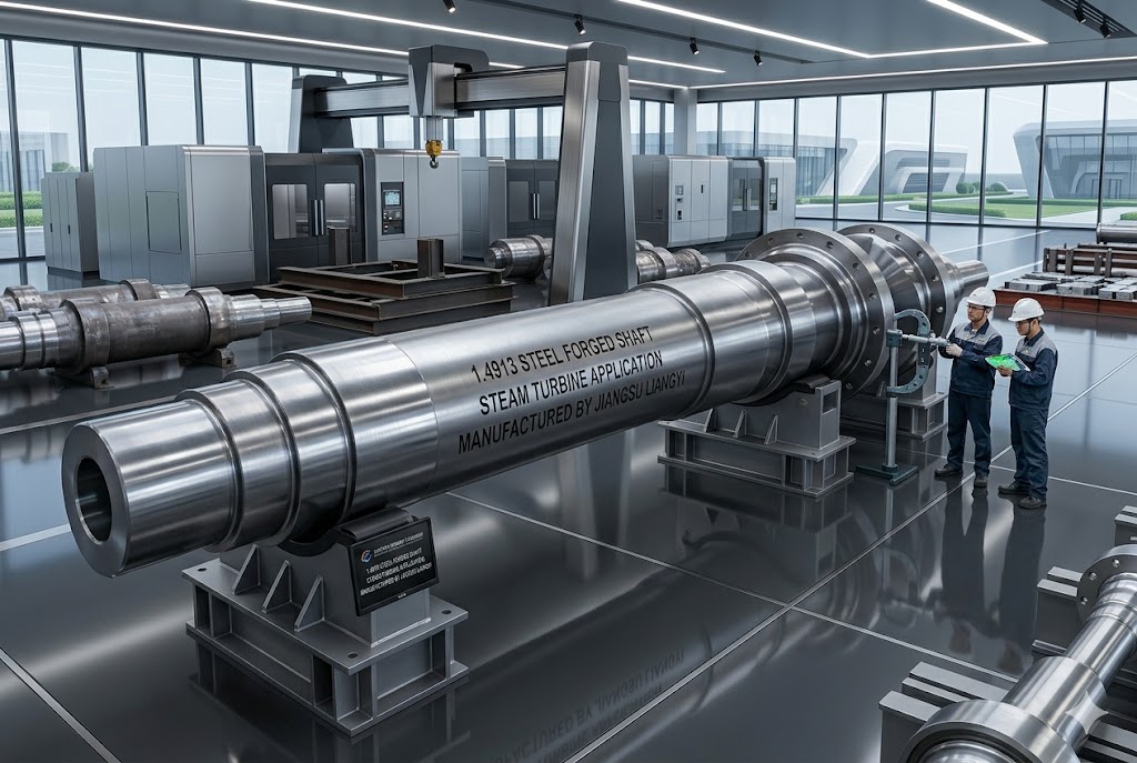
Jiangsu Liangyi Co., Limited is a professional ISO 9001:2015 certified manufacturer of 1.4913 (19CrMoVNbN11-1 / X19CrMoNbVN11-1) open die forging parts. With over 25 years of experience and state-of-the-art facilities in Jiangyin, Jiangsu Province — China's leading forging industry cluster — we supply high-quality 19CrMoVNbN11-1 forgings to customers in more than 50 countries worldwide.

Comprehensive 19CrMoVNbN11-1 Forging Capabilities
Our advanced forging facilities enable us to produce a complete range of 1.4913 steel products in various shapes and sizes, from small components weighing 30 kg to large forgings up to 30 tons. All products are manufactured in strict accordance with international standards (EN 10269, EN 10302) and customer drawings.
Available 1.4913 Forging Shapes and Dimensions
- Forged Bars: Round bars (up to 2000 mm diameter), square bars, flat bars, rectangular bars and rods
- Seamless Rolled Rings: Up to 6000 mm outer diameter, including guide rings, seal rings, labyrinth rings and casing rings
- Hollow Components: Hubs, housing shells, sleeves, bushes, pipes and tubes (up to 3000 mm OD)
- Discs and Plates: Forged discs, blocks and plates (up to 3000 mm diameter, 20 tons weight)
- Turbine Components: Gas and steam turbine rotors (up to 15 m length), shafts, blades, vanes and valve spindles
- Fasteners: Double-headed studs, bolts and nuts for high-temperature flange joints
Material Science: Chemical Composition & Alloying Mechanism
19CrMoVNbN11-1 is a corrosion-resistant high-temperature martensitic steel engineered specifically for demanding power engineering applications. Unlike conventional 9–12% Cr steels that rely primarily on solid-solution strengthening, 1.4913 achieves its elevated-temperature performance through a carefully balanced combination of three simultaneous strengthening mechanisms: solid-solution hardening (Mo, W), MX-type precipitation hardening (VN, NbC, NbN), and stable lath martensite matrix. This layered approach to microstructural design is what allows 1.4913 to maintain structural integrity at temperatures where conventional ferritic or austenitic steels would either lack strength or suffer inadequate corrosion resistance.
Applicable International Standards
EN 10269 — Steels and nickel alloys for fasteners with specified elevated and/or low temperature properties
EN 10302 — Steels and nickel alloys for the manufacture of valves for internal combustion engines
Chemical Composition of 19CrMoVNbN11-1 (1.4913)
| Element | Range (%) | Role in Alloy |
|---|---|---|
| Carbon (C) | 0.17–0.23 | Strengthens martensite matrix; supports carbide precipitation |
| Silicon (Si) | max. 0.50 | Deoxidizer; minor solid-solution strengthener |
| Manganese (Mn) | 0.40–0.90 | Deoxidizer; improves hardenability; replaces some Ni |
| Phosphorus (P) | max. 0.025 | Residual impurity; controlled to preserve toughness |
| Sulfur (S) | max. 0.015 | Residual impurity; strictly limited for ductility |
| Chromium (Cr) | 10.0–11.5 | Primary corrosion/oxidation resistance; martensitic stability |
| Nickel (Ni) | 0.20–0.60 | Improves toughness; stabilizes austenite during solution treatment |
| Molybdenum (Mo) | 0.50–0.80 | Solid-solution strengthener; retards dislocation movement at high temp |
| Vanadium (V) | 0.10–0.30 | Forms fine VN and V₄C₃ precipitates that pin dislocations |
| Niobium (Nb) | 0.25–0.55 | Forms NbC/NbN precipitates; refines austenite grain size |
| Nitrogen (N) | 0.05–0.10 | Stabilizes MX precipitates at high temperature; grain refiner |
| Aluminum (Al) | max. 0.020 | Deoxidizer; limited to prevent AlN formation reducing toughness |
| Tungsten (W) | 0.25–0.55 | Additional solid-solution hardener; improves creep above 550°C |
| Boron (B) | max. 0.0015 | Segregates to grain boundaries; improves creep rupture ductility |
Why Multi-Element Alloying Outperforms Single-Element Optimization
A key design principle of 19CrMoVNbN11-1 is that each alloying element is present at a concentration chosen to complement the others rather than to maximize any single property. For example, vanadium and niobium are both MX-forming elements, but they form precipitates of different sizes and stabilities: NbC/NbN precipitates are coarser and more thermally stable, acting as long-term grain boundary pinning agents, while VN precipitates are finer and more numerous, providing the primary resistance to dislocation glide. The addition of nitrogen simultaneously increases the volume fraction of both and shifts their dissolution temperature upward, ensuring they remain effective at 580–600°C where V-only or Nb-only steels would experience significant precipitate coarsening and strength loss.
Tungsten, present in the range 0.25–0.55%, contributes solid-solution hardening of the ferrite matrix without forming its own precipitate phase — it works cooperatively with molybdenum rather than redundantly. This cooperative effect means the combined W+Mo solid-solution hardening contribution is greater than either element alone at the same total concentration, an effect confirmed by elevated-temperature tensile and stress-rupture data on modified 12Cr steels.
Engineering Insight: The boron addition (max. 0.0015%) in 19CrMoVNbN11-1, though tiny, is critical. Boron segregates preferentially to prior austenite grain boundaries during tempering, where it suppresses grain-boundary sliding — one of the dominant creep damage mechanisms above 550°C. This is why 1.4913 exhibits significantly better creep rupture ductility (reduction of area at fracture) compared to boron-free 12Cr steels of similar composition.
Physical & Thermal Properties of 19CrMoVNbN11-1 (1.4913)
Physical properties are essential for component design, finite element analysis (FEA), and thermal stress calculations. The following data represents typical measured values for 1.4913 in the quenched and tempered condition; all values are temperature-dependent and should be confirmed against actual test certificates for critical calculations.
Density and Elastic Constants
| Temperature (°C) | Density (g/cm³) | Elastic Modulus E (GPa) | Shear Modulus G (GPa) | Poisson's Ratio ν |
|---|---|---|---|---|
| 20 | 7.75 | 215 | 83 | 0.28 |
| 100 | 7.73 | 211 | 81 | 0.28 |
| 200 | 7.71 | 205 | 79 | 0.29 |
| 300 | 7.68 | 198 | 76 | 0.29 |
| 400 | 7.65 | 190 | 73 | 0.30 |
| 500 | 7.62 | 182 | 70 | 0.30 |
| 600 | 7.59 | 173 | 66 | 0.30 |
Thermal Properties
| Temperature (°C) | Thermal Conductivity λ (W/m·K) | Mean Linear Expansion α (×10⁻⁶/K, from 20°C) | Specific Heat Capacity c (J/kg·K) |
|---|---|---|---|
| 20 | 26.0 | — | 490 |
| 100 | 26.5 | 10.5 | 500 |
| 200 | 27.0 | 10.8 | 515 |
| 300 | 27.5 | 11.0 | 530 |
| 400 | 28.0 | 11.3 | 545 |
| 500 | 28.5 | 11.6 | 555 |
| 600 | 29.0 | 11.8 | 570 |
Additional Physical Data
- Electrical Resistivity: ~0.70 μΩ·m at 20°C; ~1.10 μΩ·m at 600°C
- Thermal Diffusivity: ~6.8 mm²/s at 20°C
- Magnetic Properties: Ferromagnetic in the martensitic condition; becomes paramagnetic above the Curie temperature (~750°C)
- Melting Range: Approximately 1400–1450°C
- AC₁ Temperature (start of austenitization on heating): ~830°C
- AC₃ Temperature (complete austenitization): ~950°C
- Ms Temperature (martensite start on cooling): ~280–320°C
Design Note: The relatively low thermal expansion coefficient of 19CrMoVNbN11-1 (~11.8 × 10⁻⁶/K to 600°C) compared to austenitic steels (~17–18 × 10⁻⁶/K) means that 1.4913 components experience significantly lower thermal stresses during heat-up and cool-down cycles. This is a decisive advantage in steam turbine design, where differential thermal expansion between rotor and casing can cause rubbing and seal damage. Engineering calculations using these published values should always be verified with measured data from actual heat/lot certificates supplied with Jiangsu Liangyi forgings.
Precision Heat Treatment Process for 19CrMoVNbN11-1
All 19CrMoVNbN11-1 forged products are delivered in fully quenched and tempered (+QT) condition. The heat treatment process is strictly controlled — each furnace cycle is logged with time-temperature records supplied as part of the EN 10204 3.1 certificate package.
Standard Heat Treatment Parameters
- Normalization / Austenitization (Quenching): 1100–1130°C, held for minimum 1 hour per 25 mm section thickness, then air-cooled or oil-quenched depending on section size
- Tempering: 670–750°C, minimum 2-hour hold at temperature, followed by air cooling
- Soft Annealing (if required before machining): 820–870°C, slow furnace cooling to below 600°C at a rate not exceeding 20°C/hour
Rationale for the High Austenitization Temperature
The choice of 1100–1130°C for austenitization — higher than typical for 9–12% Cr steels — is deliberate. At this temperature, the MX precipitates (NbC, NbN, VN) dissolve back into solution, ensuring a homogeneous austenite from which, on cooling, a fully martensitic microstructure forms. This complete dissolution is essential: undissolved carbides at austenitization temperatures below ~1050°C would deplete the matrix of Nb and V, reducing the volume fraction of strengthening precipitates that re-form during tempering and in-service aging.
Stress Relief After Straightening
If straightening is necessary after heat treatment (for long bars or shafts), mandatory stress relief annealing must be performed at 20–30°C below the actual tempering temperature used, with a minimum 2-hour hold and slow cooling at ≤30°C/hour down to 300°C, then air cooling. Skipping this step introduces residual bending stresses that can cause warping during finish machining or, in the worst case, stress corrosion cracking in service.
Effect of Section Thickness on Properties
19CrMoVNbN11-1 is an air-hardenable steel with excellent hardenability. In sections up to 300 mm diameter, a fully martensitic microstructure is achievable by air cooling from the austenitizing temperature. For larger sections, oil quenching is recommended to ensure adequate cooling rates at the center. Jiangsu Liangyi routinely produces fully heat-treated forgings up to 2000 mm diameter with center mechanical properties compliant with EN 10269 requirements, verified by destructive testing of prolongation test coupons representing the center of the forging cross-section.
Guaranteed Mechanical Properties of 19CrMoVNbN11-1 (1.4913)
Every production lot undergoes full mechanical testing — tensile, impact (Charpy V-notch), and hardness — with test specimens taken from the center of one bar per heat treatment batch. The following properties are guaranteed at room temperature (+20°C) after quenching and tempering (+QT):
| Property | Symbol | Min. Specified Value | Typical Achieved Range | Test Condition |
|---|---|---|---|---|
| Tensile Strength | Rm | 900 MPa | 900–1050 MPa | +QT, longitudinal |
| 0.2% Proof Strength | Rp0.2 | 750 MPa | 750–850 MPa | +QT, longitudinal |
| Elongation at Fracture | A | 12% | 14–18% | +QT, 5d gauge |
| Reduction of Area | Z | 40% | 45–55% | +QT, longitudinal |
| Impact Energy (V-notch) | KV | 20 J at +20°C | 25–35 J at +20°C | +QT, transverse |
| Brinell Hardness | HBW | — (informative) | 280–320 HBW | +QT |
| Vickers Hardness | HV | — (informative) | 295–336 HV | +QT |
Important: The specified minimum values above represent the guaranteed floor for EN 10269 compliance. Actual production values consistently exceed these minimums. When specifying 1.4913 forgings, customers may define a target property window (e.g., Rm 950–1020 MPa) rather than just a minimum — Jiangsu Liangyi's heat treatment capability can accommodate such tighter windows.
Elevated-Temperature Strength & Creep Rupture Data
For any application above 400°C, room-temperature tensile data is insufficient for design — engineers must use elevated-temperature proof strength and, for sustained loading, creep rupture data. The following values represent typical published data for 19CrMoVNbN11-1 (1.4913) in the +QT condition; actual measured values from each production heat are available in the certified mill test report.
Elevated-Temperature Tensile Properties
| Temperature (°C) | 0.2% Proof Strength Rp0.2 (MPa, typical) | Tensile Strength Rm (MPa, typical) | Elongation A (%) |
|---|---|---|---|
| 20 | 750–850 | 900–1050 | 14–18 |
| 100 | 710–800 | 870–1000 | 15–19 |
| 200 | 680–770 | 840–970 | 15–19 |
| 300 | 660–750 | 800–930 | 15–20 |
| 400 | 640–730 | 760–880 | 15–20 |
| 500 | 610–700 | 690–810 | 16–21 |
| 550 | 580–660 | 640–750 | 17–22 |
| 600 | 520–600 | 560–660 | 18–24 |
| 650 | 390–460 | 430–520 | 20–28 |
Creep Rupture Strength — The Critical High-Temperature Design Parameter
For components under sustained stress at elevated temperatures, the governing design criterion is creep rupture strength: the stress that causes fracture after a defined time at temperature. For power plant components, the standard reference time is 100,000 hours (approximately 11.4 years) of continuous operation. The following table presents typical 100,000-hour creep rupture strength values for 1.4913, which form the basis of allowable stress values in pressure vessel and turbine design codes.
| Temperature (°C) | 10,000 h (MPa) | 30,000 h (MPa) | 100,000 h (MPa) | Comparison Context |
|---|---|---|---|---|
| 500 | ~350 | ~290 | ~230 | Comfortably above typical design stresses |
| 550 | ~235 | ~190 | ~150 | Good margin for 550°C service |
| 575 | ~185 | ~148 | ~115 | Suitable for high-efficiency plant designs |
| 600 | ~130 | ~108 | ~95 | Reference temperature for ultra-supercritical plant |
| 625 | ~90 | ~72 | ~58 | Approaching upper design limit |
| 650 | ~58 | ~45 | ~35 | Marginal; alternative alloys typically preferred |
Practical Insight — Why 600°C is the Design Boundary: The 100,000-hour creep rupture strength of 19CrMoVNbN11-1 at 600°C (~95 MPa) corresponds to an allowable design stress of approximately 47–63 MPa depending on the applied safety factor (typically 1.5–2.0×). For rotor shafts and turbine discs, the centrifugal hoop stresses in the bore region are typically designed to stay within this allowable range. At 625°C, the rupture strength drops to ~58 MPa, reducing the allowable stress to ~29–39 MPa — too low for many practical rotor geometries without significantly increased cross-sections. This is the quantitative reason why 19CrMoVNbN11-1 is not recommended for continuous service above 600°C: it is not that the steel "fails" immediately above this temperature, but that the available rupture strength becomes structurally insufficient for typical component geometries within the target service life.
Creep Deformation Rate (Steady-State Creep)
In addition to rupture strength, designers often need to know the steady-state creep rate to figure out how the component's dimensions will change over its service life. At 600°C and 100 MPa of stress, 1.4913's minimum creep rate is about 3–8 × 10⁻⁹ per hour, which is about 0.003–0.008% strain accumulation per 1000 hours. When a 500 mm-long turbine blade is working in these conditions, it stretches about 0.015–0.040 mm every 10,000 hours. This is something that needs to be taken into account when designing clearances between the rotating blades and the stationary casing. Jiangsu Liangyi can give you estimates of creep deformation for specific parts based on their shape and how they will be used.
Oxidation & Steam Corrosion Resistance of 1.4913 Steel
The 10–11.5% chromium content of 19CrMoVNbN11-1 enables it to form a continuous, adherent Cr₂O₃-rich protective oxide scale during elevated-temperature service. This scale acts as a diffusion barrier that dramatically reduces the rate of further oxidation. The quality of this scale, and thus the oxidation resistance, is strongly dependent on surface condition, temperature, atmosphere composition, and thermal cycling frequency — all factors that Jiangsu Liangyi engineers routinely consider when advising on surface finish specifications for delivered forgings.
Oxidation Resistance in Dry Air
| Temperature (°C) | 100 h exposure | 1,000 h exposure | 10,000 h exposure (estimated) | Oxide Scale Character |
|---|---|---|---|---|
| 500 | < 0.05 | < 0.15 | < 0.50 | Thin, fully protective Cr₂O₃ |
| 550 | 0.05–0.12 | 0.18–0.35 | 0.60–1.10 | Protective, minor spallation on cycling |
| 600 | 0.10–0.25 | 0.40–0.80 | 1.20–2.50 | Protective with increasing Fe₂O₃ at surface |
| 650 | 0.30–0.70 | 1.20–2.50 | 4.00–8.00 | Accelerating oxidation; scale spallation begins |
| 700 | 1.00–2.50 | 4.50–9.00 | > 15 | Breakaway oxidation regime; not recommended |
Steam Oxidation (High-Pressure Steam Environment)
In high-pressure steam environments — the primary service condition for power plant turbine blades — the oxidation mechanism differs from dry air. Steam promotes the formation of a duplex magnetite (Fe₃O₄) + hematite (Fe₂O₃) outer scale layer above the Cr₂O₃ inner layer. This duplex scale is less mechanically stable and more prone to spallation during thermal cycling. For 19CrMoVNbN11-1 in steam at 600°C, typical mass gain values after 10,000 hours are in the range of 1.5–3.5 mg/cm², compared to 1.2–2.5 mg/cm² in dry air — an approximately 40% increase in oxidation rate. At 550°C in steam, the mass gain after 10,000 hours is typically 0.8–1.5 mg/cm², which is considered acceptable for most turbine designs with 100,000-hour inspection intervals.
The practical consequence of steam-accelerated oxidation for turbine blade design is that surface allowances of 0.2–0.5 mm per surface are typically included in the as-forged dimensions to accommodate metal loss over the planned inspection interval. Jiangsu Liangyi can adjust forging dimensions to include these surface allowances per customer specification.
Resistance to Sulfidation and Flue Gas Corrosion
In power plant environments, turbine casings and valve bodies may be exposed to flue gases containing SO₂ and H₂S at temperatures up to 550°C. The 11% chromium content of 19CrMoVNbN11-1 makes it resistant to sulfidation at service temperatures up to about 540°C. When the temperature rises above this point, chromium sulfide (CrS) phases start to form and break down the protective Cr₂O₃ oxide scale. For parts that are continuously exposed to sulfur-rich flue gases above 540°C, supplementary surface protection — including aluminide and chromide diffusion coatings — is strongly recommended. The technical team at Jiangsu Liangyi can provide professional recommendations on tailored surface treatments for high-sulfidation industrial working conditions.
Comparative Corrosion Resistance
Relative to other common turbine steels, 19CrMoVNbN11-1's oxidation resistance ranks as follows: 1.4913 ≈ X20CrMoV11-1 > P91 (1.4903) > P92 (1.4901). The 11Cr steels (1.4913 and 1.4922) have approximately 15–25% lower steam oxidation rates than the 9Cr steels (P91, P92) at equivalent temperatures. This difference is significant at 580–600°C and is one reason why 11Cr steels are preferred for solid turbine blade and valve spindle applications where surface quality must be maintained over long service intervals.
International Grade Equivalents of 19CrMoVNbN11-1 (1.4913)
19CrMoVNbN11-1 is a distinctively European steel grade developed within the EN standardization framework. Unlike mainstream structural steels or stainless steels, it does not have a single universally recognized equivalent in other national standards. The following table provides the closest equivalents and near-equivalents in major international standards, along with important caveats about compositional differences that affect interchangeability.
| Standard System | Designation | Equivalence Level | Key Differences / Notes |
|---|---|---|---|
| EN (European) | 19CrMoVNbN11-1 / X19CrMoNbVN11-1 / 1.4913 | Reference Standard | Primary designation; covered by EN 10269 and EN 10302 |
| DIN (former German) | X20CrMoWV121 (partial historical precedent) | Near-equivalent (older) | Former DIN grade predating EN consolidation; lower Nb and N content; lower creep strength above 550°C |
| ASTM (USA) | No direct equivalent. Closest: A565 Gr. 616 (12Cr-Mo-V) | Approximate / OEM specs only | A565 Gr. 616 lacks Nb and N additions; significantly lower creep rupture strength at 600°C. OEM turbine specs (e.g. GE, Siemens proprietary grades) may match 1.4913 composition directly |
| ASME (USA) | No ASME standard coverage for this exact grade | Not covered | Custom ASME Code Case or purchaser specification required; Jiangsu Liangyi can supply with additional ASME-compatible documentation upon request |
| BS (UK) | BS 970 / BS EN 10269 — same as EN (post-1993 harmonization) | Direct equivalent | UK adopted EN standards; pre-harmonization BS grade was different composition. Modern BS EN = EN standard |
| JIS (Japan) | No direct JIS equivalent | Not covered | Japanese 11–12Cr turbine steels are covered by proprietary OEM specifications (MHI, Toshiba, Hitachi) rather than JIS standards; composition details are not publicly available for comparison |
| GOST (Russia) | 15Kh12VMF (ЭИ802, ЭИ579) — approximate | Near-equivalent (composition differs) | GOST 15Kh12VMF is a 12Cr-Mo-V-W steel without the Nb and N additions of 1.4913; it has lower creep strength above 560°C. Used for similar applications in Russian power plants |
| GB/T (China) | No GB/T standard covering this grade; imported material must use EN designation | Not standardized | Chinese power plant procurement that requires 1.4913 specifies EN 10269 / EN 10302 directly. Jiangsu Liangyi can supply with Chinese inspection witness (CQNPC, TÜV China) upon request |
| UNS (USA alloy registry) | No registered UNS number for this exact composition | Not registered | Some compositionally similar proprietary alloys may have UNS numbers; confirm with alloy supplier |
Critical Note on Grade Substitution: Grade "equivalents" listed above as "near-equivalent" or "approximate" should not be used as direct drop-in substitutes without engineering review. The Nb + N additions in 19CrMoVNbN11-1 are primarily responsible for its superior creep rupture strength above 550°C — grades lacking these additions (such as A565 Gr.616) may have adequate room-temperature properties but will creep faster at elevated temperatures. Always verify that the substituted grade meets the needed creep rupture strength at the actual operating temperature before approving a material substitution.
Comparative Analysis: 19CrMoVNbN11-1 (1.4913) vs P91 vs P92 vs X20CrMoV11-1 (1.4922)
Selecting the right high-temperature Cr-Mo steel is rarely straightforward — each grade has been developed to optimize a specific balance of strength, creep resistance, corrosion resistance, weldability, and cost. The following analysis is based on Jiangsu Liangyi's direct manufacturing experience with all four grades and published European Steel Technology Platform (ESTEP) data.
Note: Values are typical for standard heat-treated conditions per respective standards. Always verify with actual test certificates for engineering calculations.
Property Comparison Table
| Property | 19CrMoVNbN11-1 (1.4913) | X20CrMoV11-1 (1.4922) | P91 (1.4903) | P92 (1.4901) |
|---|---|---|---|---|
| Cr content (%) | 10.0–11.5 | 10.0–12.0 | 8.0–9.5 | 8.5–9.5 |
| Key alloying additions | Mo, V, Nb, N, W, B | Mo, V, W | Mo, V, Nb, N | Mo, W, V, Nb, N, B |
| Tensile Strength Rm (RT, MPa) | ≥ 900 | ≥ 780 | ≥ 585 | ≥ 620 |
| 0.2% Proof Strength Rp0.2 (RT, MPa) | ≥ 750 | ≥ 590 | ≥ 415 | ≥ 440 |
| Hardness (HBW after +QT) | 280–320 | 230–290 | 190–250 | 200–265 |
| 100,000 h rupture strength at 550°C (MPa) | ~150 | ~110 | ~160 | ~200 |
| 100,000 h rupture strength at 600°C (MPa) | ~95 | ~70 | ~100 | ~130 |
| Max. recommended service temperature (°C) | 600 | 580 | 620 | 650 |
| Oxidation resistance (relative) | ★★★★☆ | ★★★★☆ | ★★★☆☆ | ★★★☆☆ |
| Weldability (relative ease) | ★★★☆☆ | ★★★☆☆ | ★★★★☆ | ★★★★☆ |
| Primary application | Turbine blades, valve spindles, fasteners, shafts | Turbine blades, valve bodies (older designs) | High-pressure boiler piping, valve castings | USC boiler tubes, headers, pipes |
| Cost (relative) | High | Medium-High | Medium | Medium-High |
| Primary standard | EN 10269 / EN 10302 | EN 10269 / EN 10302 | ASTM A182 F91 / EN 10216-2 | ASTM A182 F92 / EN 10216-2 |
When to Choose 19CrMoVNbN11-1 (1.4913)
Choose 1.4913 when your application requires all three of the following simultaneously: (1) high room-temperature tensile and proof strength for a solid component (blade, spindle, fastener, shaft); (2) good oxidation/steam corrosion resistance without coatings; and (3) sustained operation at 550–600°C with acceptable creep rates over a 100,000-hour design life. It is the material most power plant OEMs specify for turbine blade forgings in the 560–600°C steam temperature range.
When Not to Choose 1.4913
- For piping or pressure vessel applications: P91 or P92 are preferred — they are lower-cost, better standardized for pressure vessel codes (ASME, EN 13480), and have comparable or superior long-term creep rupture strength at lower wall thicknesses.
- For service above 620°C: P92 or nickel-base superalloys (Alloy 625, Alloy 718) should be evaluated — 1.4913 creep rupture strength becomes insufficient above 620°C for most structural applications.
- For highly cost-sensitive, moderate-temperature applications (≤500°C): X20CrMoV11-1 (1.4922) or even ferritic 9–12Cr steels provide adequate properties at lower material cost.
Welding Guidelines for 19CrMoVNbN11-1 (1.4913)
19CrMoVNbN11-1 is weldable but demands careful process control because of its high hardenability and the risk of cold cracking (hydrogen-induced cracking) in the heat-affected zone (HAZ). The martensitic transformation of the HAZ during cooling from welding temperatures leaves the weld area in a hard, brittle, and hydrogen-sensitive condition unless proper preheat, interpass temperature control, and post-weld heat treatment (PWHT) are applied. The following guidelines represent best practice developed from Jiangsu Liangyi's manufacturing experience and European welding code (EN ISO 15614) requirements.
Welding Process Sequence
- Pre-weld cleaning: Degrease all joint surfaces with acetone or approved solvent. Remove all oxide scale within 25 mm of the weld zone by grinding or wire brushing. Moisture contamination is a primary source of weld hydrogen — keep joint areas dry immediately before welding.
- Preheat: Heat the joint uniformly to 200–250°C minimum before initiating the arc. Use induction heating or electric resistance heating blankets for large sections; gas torch heating is acceptable for thin sections if temperature is verified by contact thermometer. Do not use the weld arc for preheating.
- Interpass temperature control: Keep 200°C minimum / 300°C maximum interpass temperature throughout the entire welding operation. Below 200°C, newly deposited beads cool into brittle martensite without adequate ductility for subsequent passes. Above 300°C, carbide precipitation at austenite grain boundaries degrades HAZ toughness.
- Welding with low-hydrogen consumables: Use only H4 or H5 hydrogen-controlled electrodes that are classified (maximum 4–5 ml/100g diffusible hydrogen). Follow the manufacturer's instructions for pre-baking electrodes (usually 300–350°C for 2 hours). After baking, store in sealed containers.
- Immediate post-weld hydrogen bake-out: Immediately after welding (while still at interpass temperature), increase to 300°C and hold for 2 hours minimum before allowing any cooling. This step is mandatory to allow diffusible hydrogen to escape from the weld metal and HAZ before the martensite transformation is fully complete. Omitting this step is the most common cause of delayed hydrogen-induced cracking in 11–12Cr steel welds.
- Controlled cooling to below 100°C: After the hydrogen bake-out, allow the weld to cool slowly to below 100°C to complete the martensitic transformation before PWHT. Do not cool to room temperature and then reheat to PWHT temperature without first confirming complete martensitic transformation by hardness survey.
- Post-Weld Heat Treatment (PWHT): Heat to 720–750°C, hold for a minimum of 2 hours (or 1 hour per 25 mm thickness for sections >50 mm), then cool at a controlled rate not exceeding 100°C/hour to below 300°C, then air cool. PWHT simultaneously tempers the as-welded martensite, restores toughness, and relieves residual welding stresses.
- Post-PWHT inspection: Perform hardness survey, visual inspection, and needed NDT (MT or PT, UT for full-penetration welds) after PWHT to verify joint quality.
Recommended Filler Metals
| Welding Process | AWS Classification | EN ISO Classification | Notes |
|---|---|---|---|
| SMAW (MMA) | E410NiMo-15 (matching) or E9015-B9 (near-match) | E 19 9 NL B 4 2 H5 | Matching Cr filler for best corrosion/oxidation match; control H₂ carefully |
| GTAW (TIG) | ER410NiMo or proprietary OEM spec filler | W 19 9 NL | TIG preferred for root passes; use argon shielding + backing gas |
| GMAW (MIG) | ER410NiMo or proprietary wire | G 19 9 NL | Use only for fill and cap passes; ensure H₂-controlled shielding gas |
| SAW | Not recommended for thin components; OK for heavy repairs | — | High heat input of SAW risks excessive grain coarsening in HAZ |
| Dissimilar (to carbon/low-alloy steel) | ENiCrFe-2 or ENiCrMo-3 (Inconel type) | E Ni 6182 / E Ni 6625 | Nickel-base filler used at interface to accommodate CTE mismatch; PWHT temperature must be agreed with base metal requirements |
Critical Warning — Carbon Steel Filler Incompatibility: Under no circumstances should carbon steel or low-alloy steel filler metals (E7018, ER70S-6, etc.) be used to weld 19CrMoVNbN11-1 base metal, even for tack welds or temporary attachments. Carbon steel weld metal deposited on 1.4913 will have a coefficient of thermal expansion ~30% higher than the base metal, creating severe thermal fatigue stresses during thermal cycling that lead to premature weld cracking. All tack welds, bridge pieces, and lifting lug attachments must use the same specification filler metal as the production weld.
Machining & Fabrication Guidelines for 1.4913 Forgings
19CrMoVNbN11-1 in the quenched and tempered condition (280–320 HBW) presents moderate machining difficulty — harder and more abrasive than carbon steel, but significantly more machinable than austenitic stainless steels or nickel-base alloys. The following guidelines are based on Jiangsu Liangyi's in-house CNC machining experience with 1.4913 forgings up to 2000 mm diameter and 15 m length.
Machining Sequence Recommendation
For the best dimensional stability and surface integrity, the recommended sequence is:
- Rough machining in soft-annealed condition (if very large material removal is required): Remove 70–80% of the machining allowance before heat treatment to minimize distortion during quenching
- Heat treatment (quench + temper) of the near-net rough-machined forging
- Stress relief check / straightening if required (followed by stress relief annealing as described above)
- Semi-finish machining in the +QT condition: Remove a further 15% of allowance; verify dimensions before finish machining
- Finish machining to final dimensions: Remove remaining material with fine cuts to achieve specified surface finish
- NDT inspection on finished machined surface before delivery
Recommended Cutting Parameters
| Operation | Tool Material | Cutting Speed vc (m/min) | Feed f (mm/rev) | Depth of Cut ap (mm) | Coolant |
|---|---|---|---|---|---|
| Rough Turning | Uncoated WC-Co or TiN-coated carbide (ISO P30-P40) | 80–120 | 0.30–0.60 | 3.0–8.0 | Flood (soluble oil emulsion) |
| Semi-finish Turning | PVD TiAlN-coated carbide (ISO P20-P30) | 100–140 | 0.15–0.30 | 1.0–3.0 | Flood |
| Finish Turning | PVD TiAlN or CBN-tipped insert | 120–160 | 0.05–0.15 | 0.3–1.0 | Flood or MQL |
| Milling (face / slot) | TiAlN-coated carbide end mill | 60–100 | 0.08–0.20 per tooth | Radial: 30–50% dia; Axial: 0.5–2.0× dia | Flood |
| Drilling | Solid carbide or TiN-coated HSS-Co | 20–40 | 0.05–0.15 | Full diameter | High-pressure through-coolant recommended |
| Grinding (cylindrical) | CBN or Al₂O₃ wheel (46–60 grit, resin bond) | 18–30 m/s (wheel) | 0.003–0.010 | 0.01–0.05 | Flood (low concentration soluble oil) |
| Thread Machining | Carbide tap or thread mill | 8–15 | = thread pitch | — | Flood, high pressure preferred |
Achievable Surface Finishes
- Rough turned: Ra 3.2–6.3 μm
- Semi-finish turned: Ra 1.6–3.2 μm
- Finish turned: Ra 0.8–1.6 μm
- Ground (cylindrical): Ra 0.2–0.8 μm
- Superfinished / honed: Ra 0.05–0.2 μm (achievable on journals and bearing surfaces)
Special Machining Precautions
- Work hardening tendency: 1.4913 work-hardens moderately during cutting. Always maintain positive rake angles and avoid rubbing (ensure the tool is cutting, not sliding). Dwell cuts significantly accelerate tool wear.
- Built-up edge prevention: Use PVD-coated tools rather than CVD-coated tools for finish operations — PVD coatings have smoother surfaces that resist chip adhesion on the difficult-to-cut 11Cr matrix.
- Deburring: Sharp burrs generated during machining are hazardous and can damage sealing surfaces during assembly. Deburr all edges mechanically (file, deburring tool) rather than thermally to avoid any risk of uncontrolled heating of the heat-treated component.
- Dimensional inspection temperature: According to ISO 1, all dimensional measurements must be taken at 20°C ±2°C. If this is not possible, use the thermal expansion coefficient data in the Physical Properties section above to make corrections.
- Marking and identification: Only use low-stress stamps or vibro-engraving to mark finished parts. Never use sharp punch marking on finished surfaces, as this makes stress points that can start fatigue cracks in service.
Jiangsu Liangyi Capability Note: Our in-house CNC machining center operates seven-axis turning and milling centers with maximum turning diameter 2500 mm and turning length 15,000 mm, capable of achieving Ra 0.8 μm on finished shafts and Ra 0.4 μm on seal journal surfaces without external grinding. Surface finish and dimensional reports (including 3D CMM inspection results) are provided as standard with all machined deliverables.
Comprehensive Quality Control System
At Jiangsu Liangyi, quality control begins at raw material procurement and continues through every stage of production to final shipping inspection. The following describes our standard quality assurance workflow for 19CrMoVNbN11-1 forgings.
Microstructure and Cleanliness Requirements
- Cleanliness examination per ASTM E 45 Method A on one bar per production lot
- Uniform tempered martensite microstructure; delta ferrite content <5% confirmed by metallographic examination at 100× magnification
- Inclusion content limits: "Thin series" Type A, B, C max. 2; Type D max. 2.5; "Heavy series" all types max. 1.5
- Inclusions and cavities >75 μm are strictly prohibited
Grain Size Control
Grain size 4 or finer per ASTM E112 or ISO 643 on every production heat. Deviation from the average grain size of more than 2 grain sizes is not permissible. Measurements are taken on both the softest and hardest bars from each heat treatment batch to bracket the population.
Non-Destructive Testing (NDT)
100% ultrasonic testing (UT) per ASTM A388 on all bars and forgings. Magnetic particle testing (MT), liquid penetrant testing (PT) and radiographic testing (RT) are available per customer specification or as needed by applicable standards.
Documentation and Traceability
- EN 10204 3.1 mill test certificates as standard with all orders
- EN 10204 3.2 third-party witnessed inspection available (SGS, Bureau Veritas, TÜV, DNV, ABS, LLOYDS, Intertek)
- Full heat traceability: each piece is marked with heat number, material grade, and production batch number
- Complete production records retained for minimum 10 years
Global 19CrMoVNbN11-1 Forging Application Cases
Power Generation — Asia
Project: 600 MW Thermal Power Plant Expansion, India
Products Supplied: 120 sets of 19CrMoVNbN11-1 turbine blade forgings and 8 steam turbine rotor shafts
Results: Parts have been working well for more than five years at temperatures up to 560°C without any problems. The customer has placed more orders for more units.
Oil & Gas — Middle East
Project: Offshore Oil Field Development, Saudi Arabia
Products Supplied: 500+ 1.4913 valve spindles, seat rings and fasteners for high-pressure wellhead equipment
Results: The material has excellent corrosion resistance and high-temperature strength, so that it is the best choice material for the harsh offshore environment, exceeding performance expectations.
Industrial Turbomachinery — Europe
Project: Gas Turbine Upgrade Program, Germany
Products Supplied: X19CrMoNbVN11-1 compressor blades, guide rings and labyrinth seals
Results: Our precision forgings helped improve turbine efficiency by 2.5% and extended service intervals from 24,000 to 36,000 hours.
Marine Engineering — Global
Project: LNG Carrier Propulsion System, South Korea
Products Supplied: 19CrMoVNbN11-1 forged discs, flanges and fasteners
Results: Components meet requirements of DNV, LR, and ABS and have demonstrated exceptional reliability in marine propulsion systems.
Petrochemical — North America
Project: Refinery Upgrade, United States
Products Supplied: 1.4913 seamless rolled rings, bushings and reactor internals
Results: Extended the life of the equipment by 30% compared to the materials that were used before; there have been no failures in service in over four years.
Why Choose Jiangsu Liangyi as Your 1.4913 Forging Partner in China?
Unmatched Manufacturing Capabilities
- Complete in-house production from steel melting (30 t EAF + LF + VOD) to final CNC machining
- Advanced forging equipment: 6300 T hydraulic press, 4000 T fast forging machine, 5 T electro-hydraulic hammer
- 10 heat treatment furnaces with ±5°C temperature uniformity
- Annual manufacturing capacity: 120,000 tons of forged steel products
Strategic Location
- Jiangyin, Jiangsu Province — China's largest forging industry cluster
- 150 km from Shanghai Port for fast global shipping
Quality & Certification
- ISO 9001:2015 certified
- ASTM, EN, DIN, JIS, API standard compliance
- EN 10204 3.1/3.2 MTR with all orders
- Third-party inspection: SGS, BV, TÜV, DNV, ABS
Global Customer Support
- Customers in 50+ countries across Asia, Europe, North America, Middle East and Africa
- English-speaking technical and sales support
- Custom solutions, competitive pricing and on-time delivery guarantee
Frequently Asked Questions (FAQ) About 19CrMoVNbN11-1 Forgings
What is 19CrMoVNbN11-1 steel?
19CrMoVNbN11-1 (EN material number 1.4913, symbolic designation X19CrMoNbVN11-1) is a high-temperature martensitic stainless steel standardized under EN 10269 and EN 10302. It contains 10–11.5% chromium plus molybdenum, vanadium, niobium, tungsten, nitrogen, and boron additions that generate fine MX-type carbide/nitride precipitates which pin dislocations and grain boundaries at elevated temperatures. After quenching and tempering it delivers tensile strength ≥900 MPa and 100,000-hour creep rupture strength of approximately 95 MPa at 600°C, making it the industry standard for steam turbine blades, rotor shafts, and valve spindles in power generation.
What is the difference between 19CrMoVNbN11-1 and X19CrMoNbVN11-1?
They are identical. 19CrMoVNbN11-1 is the numerical designation (EN material number 1.4913), while X19CrMoNbVN11-1 is the symbolic designation — both defined under the EN steel classification system (EN 10027-1 and EN 10027-2). Any technical datasheet, mill test certificate, or procurement document using either name refers to exactly the same alloy with the same composition limits and property requirements.
What is the ASTM equivalent of 1.4913 steel?
There is no single direct ASTM equivalent for 19CrMoVNbN11-1 (1.4913). The closest compositional relative in ASTM standards is A565 Grade 616 (12Cr-Mo-V), but it lacks the niobium and nitrogen additions that give 1.4913 its superior creep rupture strength above 550°C. For projects requiring ASTM documentation, Jiangsu Liangyi can supply 1.4913 forgings to any custom specification with the addition of ASTM-style supplementary requirements and third-party inspection. OEM turbine manufacturers typically use proprietary specifications (e.g. GE B50TF201, Siemens internal specs) that match the 1.4913 composition directly.
What is the maximum operating temperature for 1.4913 steel?
19CrMoVNbN11-1 is designed for continuous operation at up to 600°C. For short-term or transient exposure, up to 650°C is tolerable without significant property loss. The 100,000-hour creep rupture strength at 600°C is approximately 95 MPa, which corresponds to allowable design stresses of 47–63 MPa depending on the applied safety factor. Above 620°C, the available rupture strength becomes structurally insufficient for most turbine geometries — for service above this temperature, P92 (1.4901) or nickel-base alloys should be evaluated.
What are the chemical composition limits of 19CrMoVNbN11-1 (1.4913)?
Per EN 10269 / EN 10302 (mass fraction %): C 0.17–0.23, Si max. 0.50, Mn 0.40–0.90, P max. 0.025, S max. 0.015, Cr 10.0–11.5, Ni 0.20–0.60, Mo 0.50–0.80, V 0.10–0.30, Nb 0.25–0.55, N 0.05–0.10, Al max. 0.020, W 0.25–0.55, B max. 0.0015.
What are the mechanical properties of 19CrMoVNbN11-1 after quenching and tempering?
After quenching and tempering (+QT) per EN 10269: Tensile Strength (Rm) ≥900 MPa, typical 900–1050 MPa; 0.2% Proof Strength (Rp0.2) ≥750 MPa, typical 750–850 MPa; Elongation (A) ≥12%, typical 14–18%; Reduction of Area (Z) ≥40%, typical 45–55%; Impact Energy (KV) ≥20 J at +20°C, typical 25–35 J; Hardness 280–320 HBW. At 600°C, the typical proof strength is 520–600 MPa — significantly higher than comparable 9Cr steels.
What is the density and elastic modulus of 1.4913 steel?
The density of 19CrMoVNbN11-1 (1.4913) is approximately 7.75 g/cm³ (7,750 kg/m³) at room temperature. The elastic modulus (Young's modulus) is 215 GPa at 20°C, decreasing to approximately 173 GPa at 600°C. Poisson's ratio is approximately 0.28–0.30. These values are important for finite element analysis of turbine components under combined mechanical and thermal loading.
What is the standard heat treatment for 1.4913 forgings?
The standard heat treatment is quenching and tempering (+QT): austenitization at 1100–1130°C (minimum 1 hour per 25 mm section) followed by air or oil cooling to achieve a fully martensitic structure; then tempering at 670–750°C for a minimum of 2 hours, followed by air cooling. If straightening is required after heat treatment, mandatory stress relief annealing at 20–30°C below the actual tempering temperature must follow. Soft annealing (820–870°C, slow cooling) is available if machining in the soft condition is requested before final heat treatment.
How do you weld 19CrMoVNbN11-1 steel?
Welding 1.4913 requires: (1) Preheat 200–250°C before any arc is struck; (2) Maintain 200–300°C interpass temperature throughout; (3) Use only H4/H5 hydrogen-controlled filler metals (E410NiMo type or matching 11Cr filler); (4) Perform a post-weld hydrogen bake-out at 300°C for 2+ hours immediately after welding; (5) Conduct post-weld heat treatment (PWHT) at 720–750°C for minimum 2 hours, followed by controlled cooling ≤100°C/hour to below 300°C. Skipping PWHT will leave the weld zone brittle and susceptible to hydrogen-induced cracking.
How does 19CrMoVNbN11-1 compare to P91 (1.4903) and P92 (1.4901)?
19CrMoVNbN11-1 (1.4913) has the highest room-temperature strength of the three (Rm ≥900 MPa vs ≥585 MPa for P91 and ≥620 MPa for P92), better oxidation and steam corrosion resistance due to its higher Cr content (11% vs 9%), but lower 100,000-hour creep rupture strength at 600°C (~95 MPa for 1.4913 vs ~100 MPa for P91 and ~130 MPa for P92). This means 1.4913 is preferred for solid turbine components where high mechanical strength is the primary requirement, while P91/P92 are preferred for pressure piping and vessels where long-term creep under internal pressure is the governing design criterion. P92 is the superior choice for operating temperatures above 620°C.
What is the typical lead time for 19CrMoVNbN11-1 forgings?
Standard lead time is 4–6 weeks for raw forgings and 6–8 weeks for machined components from order confirmation. We also can speed up production for urgent orders. We recommend contacting our sales team with detailed drawings and quantities so we can confirm the exact production schedule and commit to a specific delivery date for your project.
Which international standards apply to 19CrMoVNbN11-1 forgings?
19CrMoVNbN11-1 (1.4913) is standardized under EN 10269 (fasteners) and EN 10302 (valve components). Jiangsu Liangyi supplies 1.4913 forgings compliant with ASTM, EN, DIN, JIS, and API standards as specified by the customer. Mill test reports are issued per EN 10204 3.1 as standard; 3.2 third-party witnessed inspection is available through SGS, Bureau Veritas, TÜV, DNV, ABS, LLOYDS, or Intertek.
Contact Us for a 19CrMoVNbN11-1 Forging Quotation
We are ready to provide you with the best price and superior quality 1.4913 forged steel products. Whether you need standard sizes or custom forgings according to your drawings, our experienced engineering and sales team is here to help.
Please send us your detailed requirements including material grade, dimensions, quantity, applicable standard and any special specifications (NDT, PWHT, third-party inspection) for a prompt and competitive quotation.
📧 Inquiry Email: sales@jnmtforgedparts.com
📞 Phone / WhatsApp: +86-13585067993
🌐 Website: https://www.jnmtforgedparts.com
📍 Address: Chengchang Industry Park, Jiangyin City, Jiangsu Province 214400, China
Get Your Free Quotation Now