1.6931 / 26NiCrMoV8-5 Forging Parts — Complete Technical Guide & China SEW 555 Manufacturer
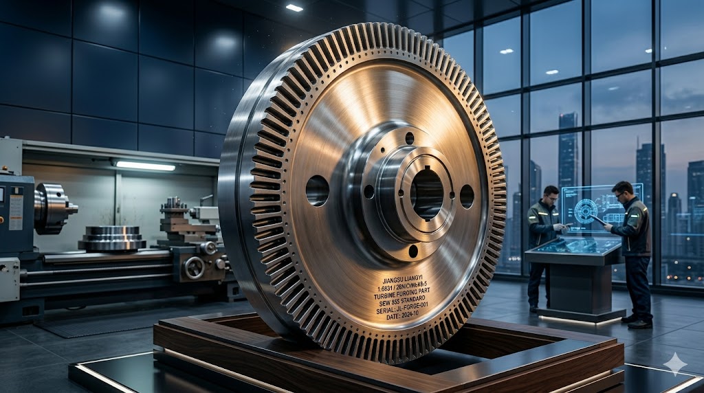
Jiangsu Liangyi Co., Limited has been manufacturing 1.6931 (26NiCrMoV8-5, also written 26NiCrMoV85, 26NiCrMoV8.5) forging parts since 1999. We operate our own EAF + LF + VOD steelmaking line, 2000T–6300T open die forging presses, 1M and 5M ring rolling mills, and a full in-house nondestructive testing laboratory — giving us direct control over every stage from liquid steel to finished certified forging. We supply power generation, oil & gas, marine and heavy industrial customers in over 50 countries, all under ISO 9001:2015 and with EN10204 3.1 material certification.
What Is 1.6931 / 26NiCrMoV8-5 Steel — Material Background & SEW 555 History
Material number per DIN EN 10027-2 steel numbering system. Commonly searched as 26NiCrMoV85, 26NiCrMoV8.5, 1.6931 steel.
The steel grade 1.6931, designated 26NiCrMoV8-5 in the DIN chemical symbol system, was developed in the 1970s by German metallurgists responding to a specific engineering problem: as steam turbine units grew larger — from 300 MW toward 600 MW and beyond — the rotor forgings required increasingly large cross-sections, and existing alloy steels could no longer deliver uniform mechanical properties throughout thick sections above 500mm diameter. The answer was a precisely balanced quaternary alloy system built around four strengthening mechanisms that complement each other without creating brittleness.
The governing specification is SEW 555 (1984) — Stähle für größere Schmiedestücke für Bauteile von Turbinen und Generatoren (Steels for Larger Forgings for Components in Turbines and Generators), published by the German Steel Federation (Stahl-Eisen-Werkstoffblatt). SEW 555 was created specifically because general structural steel standards like DIN 17200 did not address the unique combination of requirements facing turbine forgings: hardenability across sections up to 1000mm, resistance to thermal fatigue under cyclic start-stop loading, creep resistance at continuous operating temperatures up to 350°C, and the need for 100% ultrasonic inspection with a registration threshold of 3mm equivalent reflector size.
Today, 1.6931 remains the go-to specification for medium-alloy turbine forgings in the 500–800 MW class where higher-alloy grades (such as 26NiCrMoV14-5 or 30CrMoNiV5-11) are over-specified and uneconomic. It is also widely selected for gas compressor components, high-pressure valve spindles, marine propeller shafts, and heavy gear hubs where its combination of deep hardenability, good toughness, and moderate cost offers the best engineering value among SEW 555 grades.
In our 25 years of manufacturing 1.6931 forgings, the most common customer specification error we encounter is applying the wrong hardness target. Some engineers specify Brinell hardness 260–290 HBW, which requires a high tempering temperature — but at that hardness level the yield strength may drop below 590 MPa minimum. The SEW 555 specification defines mechanical properties by tensile test, not hardness. Always define acceptance by Rp0.2 and Rm, and treat hardness as a supplementary reference only. We are happy to advise on how to write correct material specifications for your application.
Metallurgical Deep Dive — How Each Alloying Element Works in 1.6931
Understanding why each element in 1.6931 is present — and why it is present in those specific ranges — is essential for both engineers specifying the material and procurement teams evaluating suppliers. A mill certificate that passes the compositional limits on paper can still produce inferior mechanical properties if the balance between elements is not optimized. This section explains the metallurgical function of each alloying element from first principles, based on our production experience with over 3,000 heats of 1.6931 steel.
Nickel is the primary toughness element. It lowers the ductile-to-brittle transition temperature (DBTT), ensuring the steel remains tough at sub-zero temperatures even in thick sections. Nickel also increases hardenability — the ability of austenite to transform to martensite rather than soft ferrite/pearlite during quenching of large cross-sections. At 1.80–2.10%, nickel does not produce temper embrittlement when combined with the controlled Mn + P levels in SEW 555. The tight range (0.30% spread) reflects the cost of nickel and the need to avoid excessive austenite stabilization that could interfere with the Ms temperature.
Chromium contributes to hardenability and forms stable carbides (Cr₇C₃, Cr₂₃C₆) that resist dissolution at austenitizing temperatures, pinning grain boundaries and limiting austenite grain coarsening. Chromium also improves high-temperature strength and oxidation resistance up to ~550°C. The 1.00–1.50% range is a deliberate compromise: above 1.5% Cr, temper embrittlement susceptibility increases sharply, especially when Mn and P are near their upper limits — a risk SEW 555 explicitly manages through the composition window.
Molybdenum plays three critical roles: (1) It is the primary anti-temper-embrittlement element — even 0.25% Mo suppresses grain boundary segregation of phosphorus that causes step-cooling embrittlement in Ni-Cr steels. (2) Mo dissolves in the iron lattice and forms fine Mo₂C carbides during tempering, contributing solid-solution and precipitation strengthening. (3) Mo raises the steel's resistance to creep at temperatures up to 400°C by slowing dislocation climb. The upper limit of 0.45% prevents excessive hardenability (which increases quench cracking risk in thick sections) and controls cost.
Vanadium is the distinguishing element that separates 1.6931 from simpler turbine steels like 34CrNiMo6. Vanadium forms extremely fine VC and V(C,N) carbonitride particles that: (1) refine prior-austenite grain size during heating (grain pinning), improving impact toughness; (2) provide secondary hardening during tempering — fine VC precipitates nucleate on dislocations and add 40–80 MPa yield strength without sacrificing ductility; (3) resist coarsening at service temperatures up to 350°C (Ostwald ripening of VC is much slower than Cr or Mo carbides), giving the steel superior long-term creep resistance. The narrow range (0.10% spread) reflects the need to avoid excessive precipitation hardening that could reduce toughness below minimum KV values.
Carbon content is deliberately moderate — high enough to form a sufficient volume fraction of carbides for strength, but low enough to maintain weldability and toughness. Carbon above 0.32% in a high-nickel steel significantly raises the martensite hardness, increasing hydrogen cracking susceptibility during water quenching of thick rotors. Our steelmaking practice targets C at 0.25–0.28% as the optimum for turbine rotor applications, allowing Q+T to achieve the required 590 MPa Rp0.2 without generating excessive residual stress during quenching.
Manganese (0.15–0.40%) is kept unusually low by structural steel standards — high Mn in combination with Ni and Cr significantly increases temper embrittlement susceptibility. Silicon (≤0.30%) is tightly limited because Si segregates to grain boundaries and promotes embrittlement. Phosphorus (≤0.015%) and sulfur (≤0.018%) are well below standard limits because in large forgings, P and S segregate to grain boundaries and the center of the ingot, creating zones of reduced toughness. Our EAF + LF + VOD route consistently achieves P ≤ 0.010% and S ≤ 0.008%, giving measurably superior center toughness compared to minimally compliant heats.
Chemical Composition of 1.6931 Forging Steel (SEW 555 — 1984)
The table below shows the SEW 555 (1984) composition limits alongside our typical production aim values, which are tighter than the specification minimums. Our aim composition reflects 25 years of production data optimization for consistent mechanical property achievement across section sizes from 100mm to 1800mm.
| Element | SEW 555 Min (%) | SEW 555 Max (%) | Our Typical Aim (%) | Metallurgical Function |
|---|---|---|---|---|
| Carbon (C) | 0.22 | 0.32 | 0.25 – 0.28 | Strength via martensite hardness and carbide formation |
| Manganese (Mn) | 0.15 | 0.40 | 0.20 – 0.35 | Deoxidation and hardenability supplement; limited to control temper embrittlement |
| Silicon (Si) | — | 0.30 | 0.10 – 0.25 | Deoxidant; tightly limited to prevent grain boundary embrittlement |
| Phosphorus (P) | — | 0.015 | ≤ 0.010 | Residual impurity; minimized to prevent center segregation embrittlement |
| Sulfur (S) | — | 0.018 | ≤ 0.008 | Residual impurity forming MnS stringers; minimized via VOD for clean toughness |
| Chromium (Cr) | 1.00 | 1.50 | 1.10 – 1.40 | Hardenability, carbide stability, oxidation resistance |
| Nickel (Ni) | 1.80 | 2.10 | 1.85 – 2.05 | Low-temperature toughness and deep hardenability in large sections |
| Molybdenum (Mo) | 0.25 | 0.45 | 0.30 – 0.40 | Anti-temper embrittlement, creep resistance, secondary hardening |
| Vanadium (V) | 0.05 | 0.15 | 0.07 – 0.12 | Grain refinement, precipitation hardening, creep resistance at 300–350°C |
A common issue in the 1.6931 market is heats supplied at the extreme ends of the composition specification — C at 0.30% combined with Mn at 0.38% and Ni at 2.08%, for example. While individually within spec, this combination produces a steel with high hardenability and poor temper embrittlement resistance, and may not reliably achieve the impact toughness minimums after step-cooling simulation per SEW 550. Always request a full mill certificate with actual heat analysis and verify that the combination of high-embrittlement-sensitivity elements (Ni + Mn + P + Si) is balanced. Our technical team can review your existing certificates at no charge.
Mechanical Properties & Heat Treatment Science of 26NiCrMoV8-5
Room-Temperature Mechanical Properties (After Q+T)
All SEW 555 mechanical properties are measured on test specimens taken from a dedicated test coupon forged integrally with or adjacent to the production forging. Test specimen location (¼ radius or center), orientation (longitudinal or tangential), and test temperature are as specified in SEW 555. Our guaranteed minimums are:
| Property | Direction | SEW 555 Minimum | Our Typical Achieved |
|---|---|---|---|
| Yield Strength (Rp0.2) | Longitudinal | ≥ 590 MPa | 620 – 720 MPa |
| Tensile Strength (Rm) | Longitudinal | 686 – 834 MPa | 700 – 800 MPa |
| Elongation (A) | Longitudinal | ≥ 20% | 20 – 24% |
| Elongation (A) | Tangential | ≥ 18% | 18 – 22% |
| Impact Toughness (KV, Charpy V) | Longitudinal | ≥ 78 J/cm² | 90 – 130 J/cm² |
| Impact Toughness (KV, Charpy V) | Tangential | ≥ 59 J/cm² | 70 – 100 J/cm² |
| Hardness (reference only) | Surface | — | 207 – 255 HBW |
Heat Treatment Process in Detail
The mechanical properties above are only achievable with precisely controlled heat treatment. Incorrect heat treatment — particularly under-tempering or non-uniform quenching — is the most common cause of property failures in large forgings. Below is our standard heat treatment protocol for 1.6931, developed over 25 years of production data:
- Preliminary Soft Annealing (if required for machining) Forgings requiring rough machining before Q+T are soft annealed at 650–680°C for 1 hour per 25mm of maximum section, furnace-cooled to below 300°C. This reduces hardness to ≤ 250 HBW for machinability while maintaining sufficient strength for handling. Not all applications require this step.
- Austenitizing — 860–890°C The forging is heated uniformly to 860–890°C (typically 880°C for turbine rotors) and held for a minimum of 1 hour per 25mm of maximum section, with an absolute minimum hold of 3 hours for large components. This temperature range dissolves most carbides into austenite while avoiding excessive grain growth — a critical balance, since grain size directly controls toughness. Atmosphere control or nitrogen blanket is used to minimize decarburization on critical surfaces.
- Quenching — Polymer or Water-Mist Spray Rapid and uniform quenching is the most technically demanding step. For forgings above 400mm section, we use a proprietary controlled spray-quench system rather than immersion quenching, which produces more uniform cooling rates across the section and reduces quench cracking risk. Cooling is controlled to achieve a surface cooling rate of ≥ 2°C/s through the martensite start temperature (Ms ≈ 360°C for 1.6931). A post-quench equalizing hold at 180–220°C for 2–4 hours is applied to reduce thermal gradients before tempering.
- Tempering — 580–650°C Tempering temperature is the primary lever for adjusting the yield strength / toughness balance. For standard SEW 555 properties (Rp0.2 ≥ 590 MPa), tempering at 600–630°C for a minimum of 4 hours per 25mm section is applied. The V-containing secondary hardening peak in 1.6931 occurs at approximately 550°C, so tempering above this temperature ensures that precipitation hardening is complete and stable, rather than occurring in service. Furnace uniformity within ±10°C is maintained using calibrated thermocouples at multiple positions within the load.
- Stress Relief Tempering (for machined parts) After rough machining, a stress relief at 580–620°C for 2–4 hours is applied to remove machining stresses before final dimensional inspection and NDE. This step prevents dimensional distortion after delivery and is mandatory for precision-tolerance components such as turbine rotor journals.
An important detail specific to vanadium-containing steels like 1.6931: if tempering is performed below 560°C in an attempt to achieve higher hardness/strength, the V(C,N) precipitates remain fine and coherent with the matrix, causing the steel to exhibit a phenomenon called "secondary hardening embrittlement" — anomalously low impact values despite passing the tensile specification. This failure mode is not visible on a standard mill certificate. The correct solution is to always temper 1.6931 above 580°C. We have encountered this issue with forgings supplied by less experienced manufacturers, and it is one reason why in-process heat treatment monitoring records are a valuable supplement to the final test certificate.
Material Comparison — 1.6931 vs Other Turbine Forging Steels
Selecting the right turbine forging steel requires understanding where 1.6931 sits within the broader family of SEW 555 and related specifications. Engineers frequently ask us to compare 1.6931 against the grades below. This comparison reflects our manufacturing experience rather than generic datasheet values, and focuses on factors that matter in real procurement and application decisions.
| Property / Factor | 1.6931 (26NiCrMoV8-5) | 34CrNiMo6 (1.6582) | 26NiCrMoV14-5 (1.6957) | 30CrMoNiV5-11 (1.7711) | 21CrMoV5-7 (1.7709) |
|---|---|---|---|---|---|
| Standard | SEW 555 | EN 10083 | SEW 555 | SEW 555 | EN 10269 |
| Min Yield Strength (Rp0.2) | ≥ 590 MPa | ≥ 700 MPa (≤63mm) | ≥ 640 MPa | ≥ 690 MPa | ≥ 550 MPa |
| Max Section Hardenability | ≈ 800 mm | ≈ 300 mm | ≈ 1500 mm | ≈ 600 mm | ≈ 300 mm |
| Vanadium addition | Yes (0.05–0.15%) | No | Yes (0.05–0.15%) | Yes (0.20–0.35%) | Yes (0.22–0.35%) |
| Creep resistance (≤350°C) | Very Good | Moderate | Excellent | Good | Very Good |
| Impact toughness (longitudinal) | ≥ 78 J/cm² | ≥ 63 J/cm² | ≥ 78 J/cm² | ≥ 78 J/cm² | ≥ 40 J/cm² |
| Temper embrittlement risk | Low–Moderate | Low | Moderate | Low | Low |
| Typical application section | 300–800 mm | ≤ 200 mm | 600–2000 mm | 200–600 mm | ≤ 300 mm |
| Primary application | HP/IP turbine rotors, compressor blades | Gears, shafts, general transmission | LP turbine rotors, generator rotors | Compressor discs, heavy shafts | Fasteners, valve stems at ≤500°C |
| Relative material cost | Medium | Low | High | Medium-High | Low-Medium |
When to choose 1.6931 over 26NiCrMoV14-5: If your rotor or disc is below 800mm effective diameter, 1.6931 is almost always the correct specification. The higher alloy content of 26NiCrMoV14-5 (higher Ni up to 3.7%) is only needed to achieve full hardening in sections above ~900mm — for smaller sections it adds cost without adding performance. We have advised several European OEMs who were over-specifying 1.6931→26NiCrMoV14-5 upgrades on their drawing packages, resulting in unnecessary 15–25% material cost increases without any measurable performance gain. Cross-referencing your maximum section size against the hardenability requirements is always the first step.
Full Range of Custom 1.6931 / 26NiCrMoV85 Forged Products
Our product portfolio for 1.6931 covers every standard forged form required by turbine, power generation, oil & gas, and heavy industrial customers. All products are manufactured in our own facilities with no outsourcing of any production step.
1.6931 Forged Bars & Rods
We produce 26NiCrMoV8-5 forged round bars (the most common form for turbine blade billets and valve spindle blanks), square bars, flat bars, and rectangular bars. Our capability: maximum diameter 2,000mm, maximum length 15,000mm, single-piece weight 30kg to 30 tons. All bars are 100% ultrasonically tested using straight-beam and angle-beam probes before dispatch. Standard supply condition is normalized + tempered or quenched + tempered as specified, with full temper annealing available for machining stocks. Dimensional tolerance is to EN 10250-2 or tighter as required.
A capability that distinguishes us from bar stockists: we produce bars directly from our own primary forging, not by reforging purchased blooms. This means full traceability from liquid steel through every heat number, forge heat, and heat treatment batch — essential for complete EN10204 3.1 material documentation requirements.
26NiCrMoV85 Seamless Rolled Forged Rings
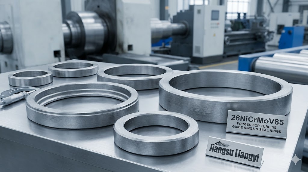
Our seamless rolled ring capability uses 1M and 5M ring rolling mills to produce rings from 300mm to 6,000mm outer diameter, with section heights from 50mm to 2,500mm and wall thicknesses from 30mm to 600mm. Maximum single ring weight is 30 tons. We produce radial-axial rolled rings (for turbine guide rings, casing rings, seal rings) and specially profiled contoured rings (for flanged rings, T-section rings, stepped bore rings) that reduce downstream machining waste.
A key technical capability for ring customers: our ring rolling is followed by a controlled ring straightening and roundness correction step before heat treatment. This produces a ring blank with diameter deviation ≤ 0.5% of OD before machining — significantly better than the EN 10250-1 standard allowance, and important for reducing machining stock allowances on large-diameter, high-wall-thickness rings where material removal is costly.
1.6931 Turbine Rotor Shafts, Monobloc Rotors & Turbine Blades
Turbine rotor shafts and monobloc rotors are our highest-value and most technically demanding product line. We produce HP (high-pressure), IP (intermediate pressure) and combined HP-IP monobloc rotors for steam turbines, as well as hollow shafts and shaft sections for gas turbines. Our largest rotor capability is 30 tons gross forging weight, corresponding to finished rotor lengths up to approximately 8 meters.
Turbine blades in 1.6931 — typically root, mid-span, and tip sections forged separately and precision machined — require tight dimensional tolerances (±0.05mm on profile dimensions) and excellent surface finish after machining. We provide both rough blade forgings (to 80% net shape) and semi-finished blade blanks to your specific profile drawings, with 100% UT and dimensional inspection certification.
Custom Industrial 1.6931 Forged Components
Beyond the above standard forms, we regularly manufacture: valve bodies and bonnets, valve spindles/stems, compressor discs, gear blanks, hub forgings, hollow bars, pressure vessel shells, flanges, marine propeller shafts, coupling hubs, and custom-profile forgings to customer drawing. All can be supplied rough forged, rough machined, or finish machined to drawing, with full inspection and certification.
Full-Process Manufacturing & Quality Control
The quality of a large 1.6931 forging is determined by hundreds of individual process decisions from the moment scrap is charged into the electric arc furnace to the moment the finished forging is cleared for dispatch. Our manufacturing system is designed so that every decision is documented, every parameter is within specification, and every deviation is recorded and reviewed. The following describes our production system in the technical detail that quality-conscious engineers need to evaluate a supplier.
Steelmaking: EAF + LF + VOD Route
Our steel is produced via a three-step refining route optimized for turbine-quality steel. The 30-ton EAF (Electric Arc Furnace) melts a carefully selected scrap charge and achieves the base carbon and alloying targets. The LF (Ladle Furnace) performs slag refining, precise alloy addition to specification, and temperature homogenization. The VOD (Vacuum Oxygen Decarburization) furnace is the critical final step: it reduces dissolved hydrogen to below 1.0 ppm (essential for large section forgings to prevent hydrogen flaking), reduces oxygen and nitrogen to achieve K4 ≤ 8 cleanliness (measured per DIN 50602), and allows final precise carbon adjustment under vacuum.
The resulting molten steel is bottom-poured into ingot molds using ladle shroud protection to prevent air reoxidation. Ingot weights range from 3 tons to 35 tons. Chemical analysis is performed on samples taken at tapping and confirmed on the finished forging per SEW 555 Section 9.
Ingot Conditioning & Pre-Forging
After solidification and stripping, ingots are allowed to cool for controlled periods before charging into the pre-heating furnace. This controlled cooling prevents thermal shock cracking in the solidified shell. Pre-heating to forging temperature (1,180–1,230°C for 1.6931) is performed in large gas-fired furnaces with automatic temperature control — soaking time is calculated based on ingot weight and geometry to ensure temperature uniformity before pressing. An ingot forged with a non-uniform temperature profile will have variable grain structure and non-uniform mechanical properties across the section.
Open Die Forging: 2000T–6300T Hydraulic Presses
Our forging floor operates three hydraulic presses with capacities of 2000T, 4000T, and 6300T. The key technical parameter for turbine forgings is forging ratio: SEW 555 requires a minimum 4:1 reduction to ensure full closure of solidification porosity and adequate grain refinement. In practice, we target forging ratios of 5:1 to 8:1 for turbine rotor quality, with multiple re-heats as required to maintain forging temperature above 900°C — forging below this temperature in 1.6931 risks producing flow lines and adiabatic shear bands that reduce fatigue life.
Forging is performed using controlled, computer-monitored press programs that track load, stroke, and temperature. Die design for each forging geometry is performed using our in-house FEM simulation capability (DEFORM software), allowing us to predict and optimize grain flow, prevent surface cracking, and ensure the required forging ratio is achieved at every cross-section before the order is placed in production.
Comprehensive Inspection — What We Test and Why
Every 1.6931 forging we deliver is accompanied by a complete test documentation package. The following inspection items are performed as standard:
- Chemical Composition Analysis: Optical emission spectroscopy (OES) on both the ladle sample at tapping and a test specimen cut from the finished forging body. The forging body result is the reported value on the mill certificate.
- Tensile Testing (EN ISO 6892-1): Three sets of tensile specimens taken at ¼ radius and/or center position as specified. Yield strength (Rp0.2), tensile strength (Rm), elongation (A), and reduction of area (Z) are reported.
- Charpy V-Notch Impact Testing (ISO 148-1): Three sets of full-size 10×10mm specimens at room temperature (20°C) in both longitudinal and tangential orientations. Average and minimum individual values are reported.
- 100% Ultrasonic Testing (CSN EN 10228-3, Quality Class 3): Every square centimeter of the forging surface is covered by straight-beam (direct probe) scanning to detect internal planar defects, plus angle-beam scanning for non-planar defects. Registration level: 3mm flat-bottom hole equivalent. Class 4 (1.5mm FBH) is available on request. All relevant indications are documented with position, depth, and amplitude data.
- Micro-Cleanliness (DIN 50602, K4 Method): 10 fields examined per polished sample at 100× magnification. Acceptance: K4 ≤ 10 (our typical result: K4 ≤ 8).
- Macrostructure Etching (ASTM E381): Full transverse section etched in hot 50% HCl to reveal macrostructure, segregation patterns, and any residual porosity. Acceptance: C1 S1 R1 (our typical result: C0 S0 R0 for most heats).
- Austenite Grain Size (ASTM E112): Minimum grain size number 6 (mean grain diameter ≤ 53μm). Our typical result: 7–8 (mean diameter 32–22μm), reflecting the grain refinement benefit of controlled vanadium carbonitride pinning.
- Microstructure Examination: Optical microscopic examination at 200× and 500× magnification verifies a consistent microstructure of tempered martensite and bainite. No detrimental microstructural features are observed, including continuous carbide networks, pearlitic banding, or isolated ferrite patches—defects indicative of incomplete austenitization or insufficient forging reduction ratio.
- Hardness Survey (HBW): Reference hardness measurement at multiple positions to confirm heat treatment uniformity across the section.
- Dimension Test: Full dimensional report to customer drawing, using calibrated CMM for precision-machined surfaces and manual instruments for rough forgings, with conformance statement.
- Optional Magnetic Particle Testing (MT) and Liquid Penetrant Testing (PT) for surface defect detection on machined surfaces, per EN ISO 10228-1 or -2.
- Third-Party Witness Inspection: Full support for SGS, Bureau Veritas, TÜV, Lloyd's Register, DNV, and other authorized inspection agencies.
The complete documentation package issued with each forging includes: the EN10204 3.1 material test certificate, full chemical and mechanical test reports, UT scan records, macrostructure photographs, microstructure photographs, grain size report, cleanliness report, hardness survey, dimensional report, and heat treatment records. Permanent marking on the forging includes heat number, material number, drawing number, and lot number for full traceability.
Global Application Cases by Industry & Region
Our 1.6931 forging parts are in active service in important infrastructure across six continents. The project cases below are genuine delivery records, shared with customer permission at an appropriate level of detail. They illustrate not just our geographic reach but the technical challenges solved for each customer.
Power Generation & Steam Turbine Systems
Supercritical Thermal Power Plant — HP/IP Turbine Rotor Shafts
This project required step-cooling embrittlement testing (per SEW 550) in addition to standard SEW 555 requirements, with each heat demonstrating compliance to a stringent ΔTK limit after the 595-hour step-cool cycle — well beyond the base specification. We achieved this by tightly controlling Mn (≤ 0.28%), P (≤ 0.009%), and Si (≤ 0.18%) — the key elements in the J-factor embrittlement parameter. All supplied heats passed step-cooling testing within the required limit. The rotors have maintained stable operation since commissioning with no quality-related outages.
Long-Term Supply — 26NiCrMoV8-5 Turbine Blades & Guide Rings for Turbomachinery OEM
This European turbomachinery manufacturer qualified Jiangsu Liangyi through a competitive process that included material testing, factory audit, and a pilot delivery. The key qualification requirement was demonstrating batch-to-batch consistency in impact toughness above the SEW 555 minimum — specifically KV ≥ 90 J/cm² as a guaranteed floor. We achieved this by implementing a fixed heat composition window (Ni 1.90–2.05%, Mo 0.32–0.40%, V 0.08–0.11%) combined with a fixed tempering temperature program per section size. Consistent process capability on impact toughness has been maintained and verified through the customer's incoming inspection program over the full supply history.
Oil & Gas and Industrial Compressor Equipment
Natural Gas Field Project — 1.6931 Compressor Blades, Valve Spindles & Stud Bolts
NACE MR0175 sour service compliance requires finished hardness ≤ HRC 22 (≤ 250 HBW) at all cross-section positions in the wetted zone, achieved through precisely controlled Q+T. For this customer, valve spindles were supplied finish-machined with hardness verified at three cross-section positions per piece. Hydrogen sulfide stress corrosion cracking (SSC) resistance was demonstrated by SSC testing per NACE TM0177 Method A at 72 hours / 0.5 bar H₂S at room temperature — all specimens passed with no cracking. This level of test documentation differentiates a technically qualified forging supplier from one that merely issues a NACE-compliant certificate without actual test evidence.
Oilfield Equipment Manufacturer — 26NiCrMoV85 Seamless Rolled Rings & Valve Bodies
This customer's primary requirement was not just material compliance but supply chain resilience — they had experienced delivery disruptions from their previous supplier. Our value proposition was demonstrated through a qualified two-route supply: a standard lead time for scheduled orders, and an expedited route maintained by holding pre-forged and pre-heat-treated bar stock for quick machining and final inspection. This arrangement allowed the customer to reduce their safety stock buffer significantly while improving overall on-time delivery performance.
Marine Engineering & Heavy Industrial Machinery
Mining Mill Project — 26NiCrMoV8-5 Forged Shafts & Gear Hubs
Mining mill drives in Australia's Pilbara region operate in ambient temperatures that can drop to −10°C at night and cycle through start-stop loading many times per shift. The customer specified Charpy impact toughness at −20°C in addition to the room-temperature SEW 555 requirements — a combined requirement achievable in 1.6931 only with tight control of grain size (ASTM 7 or finer), low sulfur (≤ 0.006%), and tempering temperature at the upper end of the range (635–650°C). Our heats achieved KV well above the customer's −20°C tangential requirement, and the shafts have maintained stable operation without fatigue or impact failures throughout their documented service life.
Shipbuilding Company — 1.6931 Marine Propeller Shafts & Sealing Rings
Marine propeller shafts in 1.6931 are less common than stainless alternatives — but this customer's design required the high fatigue strength of a quenched and tempered low-alloy steel combined with external corrosion protection. We supplied the shafts with a 0.3mm phosphating layer and two-coat epoxy primer applied in-house before packing, allowing direct installation without additional surface preparation. Classification society survey witnessed all mechanical testing and dimensional inspection, issuing a certificate covering the full delivery scope.
High-Pressure Valve & Petrochemical Equipment
Our 26NiCrMoV85 valve components are specified in high-temperature, high-pressure gate valves, globe valves, and check valves for steam and process pipeline systems in petrochemical plants, LNG terminals, and power station auxiliary systems. The typical application involves valve stems and spindles operating in steam at 280–320°C and pressures of 50–200 bar — conditions where the combination of creep resistance (Mo + V), fatigue strength (controlled grain size and cleanliness), and wear resistance (surface induction hardening optional) makes 1.6931 the preferred choice over plain CrMo steels. Optional Stellite 6 or Stellite 21 hardfacing on sealing surfaces is available, applied by our in-house PTAW (Plasma Transferred Arc Welding) process and tested per AWS A5.21 requirements.
Procurement Guide — How to Correctly Specify & Buy 1.6931 Forgings
After 25 years of supplying 1.6931 to global customers, we have observed that procurement problems — delayed shipments, failed inspections, material rejections — almost always trace back to ambiguous or incomplete purchase specifications. This guide reflects the advice our technical team gives to new customers before they place their first order.
Step 1: Define the Governing Standard
Your purchase order should explicitly state "Material: 1.6931 per SEW 555 (1984)" or the specific clause of your customer's material specification that invokes SEW 555. Do not simply write "26NiCrMoV8-5" without a standard reference — this designation could theoretically be interpreted against DIN 17200 or another less stringent specification, and would not obligate the manufacturer to perform the full SEW 555 test program.
Step 2: Specify Certificate Level
We issue EN10204 3.1 material test certificates as our standard documentation for all shipments. A 3.1 certificate is signed by our authorized inspector and covers full traceability of chemical composition, mechanical test results, NDE records, and heat treatment data. This level is accepted for the vast majority of industrial, power generation, and oil & gas applications. If your project or customer requires EN10204 3.2 (which requires an additional countersignature by a customer-nominated independent inspection body), you will need to arrange a witness inspector — such as SGS, Bureau Veritas, or TÜV — to be present during testing and to countersign the certificate. We fully support third-party witness inspection and will coordinate with your nominated agency as part of our standard service.
Step 3: Define Acceptance Criteria Explicitly
The most common ambiguity we encounter: purchase orders that state "mechanical properties per SEW 555" without specifying which Table in SEW 555 applies (the standard contains multiple tables for different heat treatment conditions and section sizes). Be explicit: state the required minimum Rp0.2, Rm range, A (min), and KV (min) at the test temperature and specimen orientation relevant to your application. If you require properties at elevated temperature, state this — room-temperature test results do not imply high-temperature properties.
Step 4: State the Maximum Cross-Section
SEW 555 mechanical properties are specified for the "representative section" — typically the maximum cross-sectional dimension of the forging or a defined multiple of it. A forging manufacturer is only obligated to test properties from a test coupon representative of the maximum section actually produced. If your 800mm-diameter rotor will be tested with a coupon from a 200mm appendage, the result may not represent the actual rotor properties. Always state "test specimens from maximum section position" in your specification.
Step 5: Specify Supplementary Tests Early
Step-cooling embrittlement testing, low-temperature impact tests, elevated-temperature tensile tests, NDE beyond standard Class 3, and SSC testing for NACE compliance all add lead time and cost that must be planned into the production schedule. These tests cannot be retroactively specified after the forging is heat treated — specify them in your purchase order, or in a pre-order technical meeting. We always recommend a technical pre-order review call for first-time orders and for any project with supplementary test requirements.
Red flags when evaluating a 1.6931 forging supplier: (1) No in-house steelmaking — suppliers who purchase billets or ingots from secondary sources cannot guarantee the VOD refining route needed for large turbine forgings. (2) No VOD or VD capability — hydrogen content above 2 ppm in ingots above 3 tons cross-section will cause hydrogen flaking after cooling. (3) Mill certificate shows P at 0.014% or S at 0.016% — technically within spec, but indicates a supplier running at the edge of cleanliness requirements rather than optimizing for performance. (4) No step-cooling test data — a supplier that has never performed step-cooling testing cannot claim competence in temper embrittlement-resistant 1.6931 production. (5) No in-house NDE facility — outsourced UT means the forging manufacturer has not directly verified internal quality and cannot fully stand behind their material certificate.
Why Choose Jiangsu Liangyi as Your 1.6931 Forging Manufacturer
There are dozens of Chinese forging manufacturers. What follows is not a generic list of claimed advantages, but a specific and honest account of what distinguishes our 1.6931 capability from the typical market offering:
- Vertically Integrated, No Outsourcing: We own and operate every step: steelmaking (EAF+LF+VOD), ingot casting, open die forging (2000T–6300T), ring rolling (1M and 5M), heat treatment (10 controlled-atmosphere furnaces), CNC machining, and NDE laboratory. When you visit our factory, you see your steel being made — not purchased from a third party. This integration is rare in China at our scale and is the foundation of our quality consistency.
- 25+ Years of 1.6931 Specialization: We are not a general structural steel forger who occasionally produces turbine-grade material. 1.6931 and related SEW 555 grades form the core of our business. Our heat treatment database includes parameters optimized for 1.6931 across section sizes from 80mm to 1,800mm, developed through thousands of production heats and hundreds of first-article qualifications with global customers.
- ISO 9001:2015 Quality System & Third-Party Audits: Our quality management system is certified to ISO 9001:2015 by an internationally accredited certification body. Customers across Europe, North America, the Middle East, and Asia-Pacific have completed factory audits and approved Jiangsu Liangyi as a qualified supplier. We welcome new customer audits and provide full access to our quality documentation during qualification.
- Competitive Direct-Manufacturer Pricing: As a vertically integrated China manufacturer with our own steelmaking and forging facilities, we offer significantly more competitive pricing than trading companies or import distributors for the same technical specification, without compromising on quality or documentation standards.
- Responsive Technical Team: Our engineering team includes metallurgists with postgraduate qualifications in materials science and engineers with deep forging process experience. Technical questions receive answers within 24 hours, and our team will engage directly with your engineering or quality department — not just your procurement desk.
Explore our complete capability in forging steel materials and review our full production equipment before your next inquiry.
Technical Glossary — Key Terms for 1.6931 Forgings
A reference for engineers and procurement teams new to turbine forging steel specifications.
Stahl-Eisen-Werkstoffblatt 555 — the German Steel Federation material specification for steels used in large forgings for turbine and generator components. First published in 1969, revised in 1984 (the current and most widely used version). SEW 555 covers chemical composition, heat treatment, mechanical testing procedures, NDE requirements, and certification. It is not an EN or ISO standard, but is universally accepted by turbine OEMs globally as the governing document for medium-alloy turbine forging steels including 1.6931.
The European standard EN10204 defines types of inspection documents for metallic products. A 3.1 certificate — the level we issue as standard — is signed by our authorized quality inspector and documents the actual test results for the specific heat and lot: chemical composition, mechanical test data, NDE results, heat treatment records, and dimensional conformance. It provides full traceability from finished forging back to liquid steel. A 3.2 certificate additionally requires countersignature by the customer's own representative or a customer-nominated independent inspection body (such as SGS, Bureau Veritas, or TÜV) who witnesses the testing in person. EN10204 3.1 is accepted for the great majority of industrial, power generation, and oil & gas applications worldwide.
The stress at which a material exhibits 0.2% permanent plastic strain — the conventional yield strength for steels that do not display a sharp yield point. For 1.6931 per SEW 555: minimum Rp0.2 ≥ 590 MPa. This is the primary design parameter for turbine rotor shafts and compressor discs loaded in bending and torsion.
A phenomenon in low-alloy Ni-Cr steels where prolonged exposure to temperatures in the range 375–575°C causes phosphorus and antimony to segregate to prior-austenite grain boundaries, drastically reducing impact toughness. This is particularly critical for turbine rotors that operate continuously at 300–400°C for decades. SEW 550 defines a step-cooling test cycle (595 hours, multiple hold temperatures) to simulate in-service embrittlement and qualify steel heats for critical applications. Molybdenum additions (≥ 0.25%) are the primary countermeasure. The J-factor (J = (Mn+Si)(P+Sn) × 10⁴) is used to predict embrittlement susceptibility from composition data.
A secondary metallurgy process in which molten steel in a ladle is subjected to vacuum conditions while oxygen is injected to reduce carbon content, and argon is stirred from the bottom to promote homogenization. In turbine steel production, the primary benefit is hydrogen degassing: the reduced partial pressure of hydrogen under vacuum causes dissolved H to diffuse to the liquid surface and be evacuated. Achieving H ≤ 1.0 ppm is essential for large forgings to prevent hydrogen-induced flaking during post-forge cooling.
The ratio of the cross-sectional area of the starting material (ingot or bloom) to the cross-sectional area of the finished forging. Also expressed as a length elongation ratio. SEW 555 requires a minimum forging ratio of 4:1 for turbine forging quality, which ensures closure of solidification shrinkage porosity, breaking up of as-cast dendrite structure, and development of fibrous grain flow aligned with the primary loading direction. Higher ratios (5:1 to 8:1) further improve toughness and cleanliness in the final product.
A micro-cleanliness assessment method in which 10 microscopic fields of a polished longitudinal section are rated for non-metallic inclusions (oxides, sulfides, silicates, and global oxides) at 100× magnification. The K4 total is the sum of the maximum severity ratings across all four inclusion types. SEW 555 acceptance: K4 ≤ 10. Our production achieves K4 ≤ 8 as a process standard, with K4 ≤ 6 achievable on request for critical applications. Lower K4 directly correlates with higher fatigue life in rotating components.
A phenomenon in vanadium, molybdenum, and tungsten-bearing steels where the hardness increases during tempering at 500–600°C, rather than decreasing monotonically. The cause is the nucleation and growth of fine alloy carbide precipitates (VC, Mo₂C) that form on dislocations and lath boundaries as the initial as-quenched martensite decomposes. In 1.6931, the secondary hardening peak from VC precipitates occurs at approximately 530–560°C. Tempering well above this temperature (580–650°C) produces over-aged precipitates that provide stable, creep-resistant strengthening without the brittleness associated with the hardening peak.
Frequently Asked Questions — 10 Technical Questions About 1.6931 Forgings
These are the questions our engineering team actually receives from customers. Answers are based on our manufacturing experience, not generic textbook descriptions.