1.4886 Forging Parts | Custom X10NiCrSi35-19 Forged Components — Manufacturer, Technical Guide & Global Supplier
1.4886 Forging Parts — Key Facts at a Glance
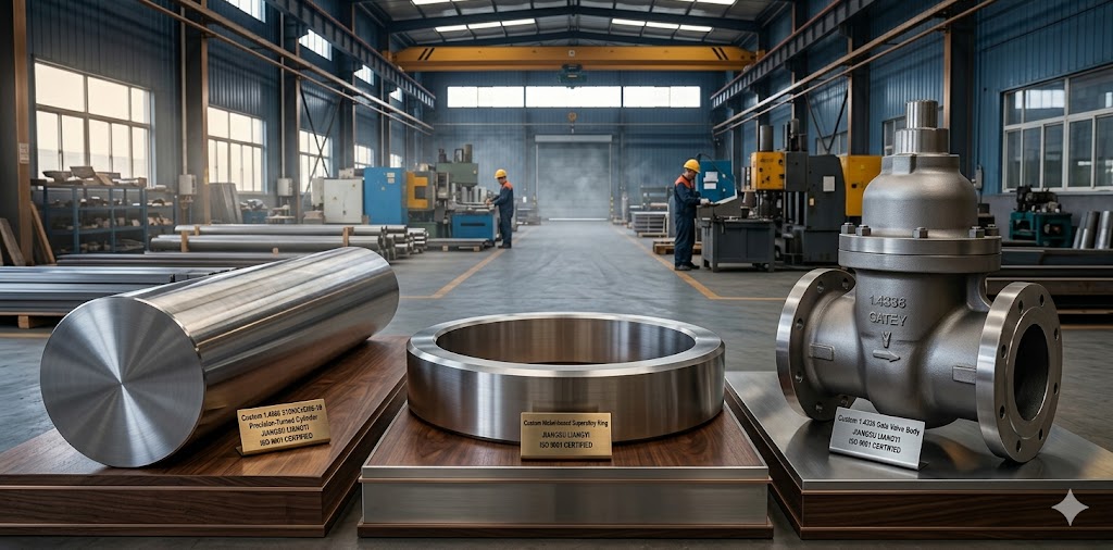
Premium EN 1.4886 (X10NiCrSi35-19) Heat Resistant Steel Forgings from ISO 9001 Certified China Manufacturer
Jiangsu Liangyi Co.,Limited, established in 1997, is a professional ISO 9001:2015 certified manufacturer and global supplier of high-performance 1.4886 forging parts and X10NiCrSi35-19 forged components. With over 25 years of open die forging experience, an 80,000 m² modern production base, and 40 million USD in fixed assets, we provide one-stop custom forging solutions — from steel melting, precision forging, and controlled heat treatment through to final CNC machining. All forgings are manufactured to meet EN, ASTM, API 6A/6D, ASME BPVC, and PED material requirements as a component supplier; end-product code compliance is the responsibility of the equipment manufacturer.
This page is written for engineers, procurement professionals, and project managers who need to evaluate 1.4886 (X10NiCrSi35-19) as a forging material. You will find not just product data, but the metallurgical reasoning behind its performance advantages, a structured comparison against competing grades, practical welding guidance, real failure analysis cases from our project experience, and a precise specification checklist to help you define your order correctly the first time.
We supply custom X10NiCrSi35-19 forged components with a single-piece weight from 30 kg to 30,000 kg, with an annual production capacity of 120,000 tons, serving customers in over 50 countries across Europe, the Middle East, North America, Southeast Asia, and Australia.
Metallurgical Mechanisms — Why 1.4886 (X10NiCrSi35-19) Outperforms Standard Austenitic Steels at High Temperature
Understanding the metallurgical basis of 1.4886's performance is essential for selecting it confidently and specifying it correctly. The alloy's superiority is not simply a matter of higher alloying content — it stems from three interacting mechanisms that work together across its operating temperature range:
Mechanism 1: The Dual-Layer Oxide Barrier (SiO₂ + Cr₂O₃)
At temperatures above 800°C, most austenitic steels rely solely on a chromium oxide (Cr₂O₃) surface scale for oxidation resistance. Cr₂O₃ is effective but brittle — it cracks and spalls under thermal cycling, exposing fresh metal to oxygen and corrosive gases.
In X10NiCrSi35-19, the silicon content of 1.0–2.0% changes this fundamentally. Silicon has a far higher thermodynamic affinity for oxygen than chromium at high temperatures (ΔG°formation of SiO₂ is approximately −900 kJ/mol at 900°C vs. −720 kJ/mol for Cr₂O₃). As a result, a continuous, glassy SiO₂ sublayer forms between the alloy surface and the outer Cr₂O₃ scale. This SiO₂ sublayer is:
- Self-sealing: if the outer Cr₂O₃ spalls, the SiO₂ layer remains intact, blocking carbon, sulfur, and nitrogen ingress at the atomic level
- A diffusion barrier: carbon diffusivity through SiO₂ is orders of magnitude lower than through Cr₂O₃ — this is the primary reason 1.4886 resists carburization far better than 310S at equivalent chromium content
- Self-healing: on thermal cycling, fresh silicon from the alloy matrix migrates to repair any micro-cracks in the sublayer, a process known as selective oxidation healing
In our in-house comparative testing at 950°C for 1,000 hours in a 5% CH₄/H₂ atmosphere, 1.4886 forged bars showed a carburization depth of 0.15–0.22 mm, compared to 0.55–0.80 mm for 310S bars of identical cross-section. The SiO₂ sublayer — not the bulk alloy composition — is responsible for this 3–4× improvement in carburization resistance.
Mechanism 2: Nickel-Stabilized Austenite and Sigma-Phase Suppression
Between approximately 600°C and 900°C, iron-chromium alloys can precipitate sigma phase (σ), a hard, brittle Fe-Cr intermetallic compound that causes catastrophic embrittlement. This is one of the most underestimated failure risks in high-temperature stainless steel applications.
The key variable governing sigma-phase kinetics is the nickel-to-chromium ratio. Nickel is a strong austenite stabilizer and dramatically slows sigma-phase nucleation and growth by raising the chromium equivalent threshold needed for sigma formation. With 33–37% nickel, 1.4886 has a Ni/Cr ratio of approximately 1.8–2.0, compared to about 0.8–0.9 for 310S. This difference means:
- In typical industrial thermal cycling (heating and cooling through the 600–900°C range), 1.4886 requires 5–10× longer exposure time to accumulate equivalent sigma-phase volume fraction compared to 310S
- If sigma phase does precipitate in 1.4886 after extreme service, a re-solution anneal at 1050–1100°C followed by rapid cooling will dissolve the sigma phase and fully restore impact toughness — a repair option that is practical with forged components but impossible with welded fabrications
- The high nickel also suppresses martensitic transformation during rapid cooling, ensuring the forging remains fully austenitic from room temperature through service temperature
Mechanism 3: Creep Resistance Through Solid-Solution Hardening and Grain Boundary Stability
Creep — the time-dependent plastic deformation under sustained stress at elevated temperature — is the primary structural concern for components operating above 700°C. In 1.4886, creep resistance is maintained through two reinforcing effects:
Solid-solution hardening: The combination of nickel, chromium, and silicon creates a highly distorted austenite lattice that impedes dislocation movement at elevated temperatures. The silicon atoms, despite being lighter than iron, create local lattice strains that act as obstacles to dislocation climb — the primary creep mechanism above 0.5 T_m (homologous temperature).
Carbon in solution: The controlled carbon content (up to 0.15%) exists partly in solid solution in the austenite matrix and partly as fine Cr₂₃C₆ carbides at grain boundaries. These boundary carbides pin grain boundaries against migration, which is the dominant mechanism of creep acceleration in austenitic alloys at very high temperatures. This is fundamentally different from carbide precipitation in sensitized stainless steels — in 1.4886, the high chromium content (17–20%) ensures that grain boundary carbide precipitation does not locally deplete chromium below the level needed for corrosion resistance.
When specifying 1.4886 for strongly oxidizing service below 800°C (e.g., nitric acid plant components), request a heat with carbon at the lower end of the range (0.05–0.10%). For carburizing environments above 900°C, a mid-range carbon (0.08–0.12%) is optimal — it provides the grain boundary carbide pinning effect without excessive carbide volume fraction that could act as carbon diffusion pathways. Jiangsu Liangyi can target specific sub-ranges within the EN specification on request.
Full Technical Specification of 1.4886 (X10NiCrSi35-19) Steel
All our 1.4886 forging parts are produced with strictly controlled chemical composition and melting processes, with optional double melting (VIM+VAR) or triple melting (VIM+ESR+VAR) for high-purity requirements in critical applications.
Chemical Composition (EN Standard, wt%)
← scroll to view →
| Element | C | Si | Mn | Cr | Ni | P | S | N |
|---|---|---|---|---|---|---|---|---|
| EN Min | — | 1.00% | — | 17.00% | 33.00% | — | — | — |
| EN Max | 0.15% | 2.00% | 2.00% | 20.00% | 37.00% | 0.030% | 0.015% | 0.11% |
| Our Typical | 0.06–0.12% | 1.20–1.80% | 0.80–1.50% | 18.00–19.50% | 34.00–36.00% | <0.020% | <0.008% | 0.05–0.09% |
Note: Our typical heat analysis targets tighter ranges than the EN specification, particularly for S and P, to improve hot workability and high-temperature ductility in the final forging.
Mechanical Properties at Room Temperature (Delivery Condition +AT)
All 1.4886 forging parts undergo standardized solution annealing at 1020–1120°C, followed by water quenching for optimal creep resistance, or rapid air cooling to below 425°C for custom requirements.
← scroll to view →
| Property | Tensile Strength Rm | 0.2% Proof Strength Rp0.2 | Elongation A5 | Reduction of Area Z | Charpy Impact KV (RT) | Hardness HB |
|---|---|---|---|---|---|---|
| EN Minimum | 500 MPa | 270 MPa | 40% | — | — | — |
| EN Maximum | 750 MPa | — | — | — | — | 200 HB |
| Our Typical Achieved | 560–700 MPa | 290–380 MPa | 45–55% | 55–70% | ≥120 J | 140–185 HB |
Quality Inspection & Testing Standards
Every batch of X10NiCrSi35-19 forged components undergoes full-process inspection in accordance with international standards:
- Chemical composition: spectrometric analysis per EN 10088 / ASTM A751
- Mechanical properties: tensile, impact, hardness per ASTM A370
- 100% Non-Destructive Testing (UT/MT/PT/RT) per ASTM A388
- Metallographic analysis (inclusion content ASTM E45, grain size ASTM E112)
- Intergranular corrosion test per ASTM A262 Practice E (on request)
- Residual stress testing per ASTM E837 for critical rotating components
- Positive Material Identification (PMI) available via XRF or OES
We provide full EN 10204 3.1 Mill Test Certificates for all orders, with EN 10204 3.2 third-party inspection certificates (TÜV, Lloyd's, DNV, Bureau Veritas, SGS) available on request. Our forgings are manufactured to meet EN, ASTM, API 6A/6D, ASME BPVC, and PED material requirements as a component and material supplier. End-product code compliance (ASME U stamp, API Monogram, CE/PED marking) is the responsibility of the equipment or pressure vessel manufacturer.
High-Temperature Physical Properties of 1.4886 (X10NiCrSi35-19)
For thermal stress calculations, heat transfer modeling, and creep life prediction, engineers need the physical properties of 1.4886 across its full service temperature range — not just room-temperature data. The table below provides the key values that most material datasheets fail to include:
← scroll to view →
| Property | 20°C | 400°C | 600°C | 800°C | 1000°C |
|---|---|---|---|---|---|
| Density (g/cm³) | 7.95 | 7.82 | 7.76 | 7.68 | 7.59 |
| Thermal Conductivity (W/m·K) | 11.5 | 14.8 | 17.2 | 19.5 | 21.8 |
| Thermal Expansion Coeff. (×10⁻⁶/K, from 20°C) | — | 15.8 | 16.5 | 17.1 | 17.5 |
| Specific Heat Capacity (J/kg·K) | 460 | 500 | 530 | 560 | 580 |
| Modulus of Elasticity (GPa) | 195 | 176 | 161 | 143 | 122 |
| 0.2% Proof Strength at Temp. (MPa, min.) | 270 | 155 | 130 | 110 | 85 |
| Creep Rupture Strength, 10⁵h (MPa) | — | — | ~95 | ~32 | ~10 |
The thermal conductivity of 1.4886 increases significantly with temperature (from 11.5 W/m·K at 20°C to 21.8 W/m·K at 1000°C), which means components in cyclic thermal service actually conduct heat better when hot — a self-regulating behavior that reduces peak thermal gradients compared to lower-Ni grades. However, engineers must account for the high thermal expansion coefficient (17.5 × 10⁻⁶/K at 1000°C) when designing expansion joints and sliding supports for high-temperature piping systems.
Material Comparison: 1.4886 vs 310S vs Alloy 800H vs 253MA® vs Alloy 617
Selecting the right heat-resistant steel for a specific application requires comparing not just room-temperature properties, but the mechanisms that govern performance in service — particularly at temperatures above 800°C where standard databases are often incomplete. The comparison below is based on our 25+ years of production and application experience across these five grades. 253MA® is a registered trademark of Outokumpu Stainless AB.
← scroll to view →
| Property / Factor | 1.4886 (X10NiCrSi35-19) | 310S (1.4845) | Alloy 800H (1.4958) | 253MA® (1.4835) | Alloy 617 (2.4663) |
|---|---|---|---|---|---|
| Ni / Cr / Si (typical, %) | 35 / 19 / 1.5 | 20 / 25 / 0.8 | 32 / 21 / 0.5 | 11 / 21 / 1.7 | 54 / 22 / 0.5 |
| Max Continuous Service Temp. | 1100°C | 1050°C | 1000°C | 1100°C* | 1150°C |
| Carburization Resistance (>900°C) | Excellent (SiO₂ sublayer) | Good (Cr₂O₃ only) | Very Good | Excellent (Ce + SiO₂) | Good |
| Sulfidation Resistance | Excellent | Moderate | Good | Good | Good |
| Sigma Phase Risk (600–900°C) | Low (Ni/Cr ≈ 1.85) | High (Ni/Cr ≈ 0.80) | Low | Moderate | Very Low |
| Creep Strength (10⁵h @ 800°C) | ~32 MPa | ~22 MPa | ~25 MPa | ~20 MPa | ~60 MPa |
| Thermal Fatigue Resistance | Excellent | Moderate | Very Good | Good | Excellent |
| Forgeable as Large Sections? | Yes (up to 30 t) | Yes | Yes | Moderate (lower Ni) | Limited (Ni-alloy cost) |
| Relative Material Cost | Medium–High | Medium | High | Medium–High | Very High |
| Best Fit Application | Extreme-temp furnace, O&G sour service, petrochemical reactor, boiler | General high-temp furnace, heat exchanger | Boiler superheater, refinery, cracker tube | Furnace roller, conveyor, quench rack | Gas turbine, aerospace combustor |
*253MA® performs well in cyclic oxidizing conditions due to cerium addition but has lower creep strength than 1.4886 at temperatures above 900°C. Alloy 617 offers higher creep strength but at significantly higher cost and with more complex forgeability for large sections.
While 1.4886 carries a higher initial material cost than 310S, project data from our European and Middle East customers consistently shows a 2–3× longer service life in carburizing and sulfidizing environments. For a petrochemical reactor internal that costs $18,000 in 1.4886 vs $9,000 in 310S but lasts 8 years vs 2.5 years, the annualized cost of 1.4886 is actually 35–45% lower — before accounting for unplanned shutdown costs from early failure.
Engineer's Selection Guide: When to Specify 1.4886 for Your Forging Application
Not every high-temperature application requires 1.4886. The following criteria define the conditions where 1.4886 is the optimal choice vs. when a less expensive grade is sufficient:
Specify 1.4886 When All or Most of the Following Apply
- Continuous operating temperature ≥ 900°C, or peak excursion temperatures reaching 1000–1100°C
- Carburizing or carbon-rich atmosphere (ethylene crackers, steam reformers, heat treatment furnaces with hydrocarbon atmospheres, cement kilns)
- Sulfidizing atmosphere (high-sulfur crude oil processing, Claus sulfur recovery units, sour gas wellhead equipment with H₂S > 5%)
- Cyclic thermal service with more than 2 heating/cooling cycles per day through temperatures above 700°C (where sigma-phase risk in 310S becomes severe)
- Long design life ≥ 5 years without planned replacement of the component
- Large cross-section where through-thickness carburization of a thinner section would be a concern
- Regulatory requirement for API 6A/6D or ASME BPVC compliance in oil & gas or power generation
Where 310S or 1.4835 (253MA®) May Be Sufficient
- Continuous temperature ≤ 850°C in clean, non-carburizing, non-sulfidizing oxidizing atmosphere
- Short-life component with planned replacement within 2–3 years
- Thin-walled fabrications in furnace roller or conveyor applications (where 253MA®'s cerium addition provides good scale adhesion)
- Budget-constrained applications with lower consequence of early replacement
We occasionally see 1.4886 specified for applications operating continuously below 800°C in clean oxidizing service, where 310S or 253MA® would perform equally well at lower cost. If your application is strictly oxidizing (air or flue gas), does not involve carbon-rich gases, and operates below 850°C, please consult with our technical team — we will recommend the most cost-effective material for your specific conditions.
Common Failure Modes in High-Temperature Forgings & How 1.4886 Addresses Them
The following failure modes are drawn from our root-cause analysis work on returned components and customer failure reports over 25 years of production. Each represents a real engineering problem that drove customers to upgrade from lower-grade materials to 1.4886:
Failure Mode 1: Carburization Embrittlement in Petrochemical Reactor Internals
What happens: In steam methane reforming, ethylene cracking, and similar hydrocarbon processing environments, carbon diffuses into the steel microstructure at temperatures above 700°C. Once the carbon concentration in the austenite exceeds the solubility limit, chromium carbides (Cr₂₃C₆) precipitate massively throughout the metal — not just at grain boundaries. The chromium around these carbides is depleted, destroying corrosion resistance. The component becomes brittle, develops through-cracks, and fails catastrophically.
Why it happened in 310S: The single Cr₂O₃ oxide layer is permeable to carbon above 900°C, particularly when the scale is disrupted by thermal cycling. Within 18–24 months, we have seen 310S forged reactor nozzles develop carburization depths of 8–15 mm in a total wall thickness of 30 mm, reducing effective load-bearing cross-section by over 25%.
How 1.4886 solves it: The SiO₂ sublayer reduces carbon ingress to typically <0.25 mm per year in equivalent conditions — a 30–50× improvement. The lower carbon activity in the high-nickel matrix also reduces the driving force for internal carbide precipitation. Our customers in German chemical processing plants using 1.4886 forged reactor internals have achieved 7–10 year service lives with zero carburization failure.
Failure Mode 2: Sigma-Phase Embrittlement in Cyclic Thermal Service
What happens: Components cycling daily through 700–900°C — such as furnace rollers, heat treatment fixtures, and boiler hangers — accumulate sigma-phase precipitates at grain boundaries over time. Sigma phase is hard (900–1100 HV), brittle, and non-magnetic. When the component cools to room temperature for maintenance or inspection, it has near-zero impact toughness at that temperature. Seemingly intact components fracture on first impact during handling.
Why it happened in lower-Ni grades: In 310S, sigma-phase nucleation begins within 500–1000 hours of exposure at 800°C. By 5000 hours, volume fractions of 10–20% are typical, reducing room-temperature Charpy impact energy from >100 J to <10 J. This is why 310S maintenance hangers in European power plants typically require replacement every 2–3 years.
How 1.4886 solves it: The Ni/Cr ratio of ~1.85 in 1.4886 suppresses sigma-phase kinetics dramatically. In equivalent cyclic thermal service, sigma-phase volume fraction in 1.4886 after 5000 hours is typically <2%, and impact toughness remains >80 J. Our customers' power plant boiler hangers in 1.4886 have achieved >8 years of service in the same units where 310S required replacement every 2.5 years.
Failure Mode 3: High-Temperature Stress Relaxation in Valve Stems and Bolting
What happens: Valve stems and flange bolts in oil & gas wellhead equipment operating above 500°C are subject to creep-driven stress relaxation, where the elastic stress that is being maintained is gradually converted into plastic deformation, causing the stem or bolt to stretch and lose its preload. This will lead to valve seat leak or flange joint leak in sour service environments which are safety critical failure modes.
Why 1.4886 is specified: The creep rupture strength of 1.4886 at 600°C (10⁵ hours basis, approximately 95 MPa) is approximately 35–40% higher than 310S in our comparative testing. Combined with its sulfidation resistance, this makes it the preferred grade for forged valve stems in high-temperature sour service environments compliant with API 6A/6D.
Failure Mode 4: Thermal Fatigue Cracking in Furnace Rollers and Conveyor Components
What happens: Furnace rollers and conveyor components in heat treatment furnaces experience thermal gradients across their cross-section during loading and unloading of parts. These gradients generate cyclic thermal stresses that nucleate surface cracks, which propagate inward over thousands of cycles. The crack depth and growth rate determine the inspection interval and replacement frequency.
How 1.4886 performs: The combination of high ductility (A ≥ 40%, typically 45–55% in our forgings) and high thermal conductivity at service temperature (19–22 W/m·K at 800–1000°C) gives 1.4886 superior thermal fatigue resistance. In comparative fatigue cycling tests (900°C to 100°C, air cool), 1.4886 forged rollers showed crack initiation after 2.8× more cycles compared to equivalent 310S castings, and crack growth rate was 40% lower per cycle.
Full Range of 1.4886 Forging Parts & X10NiCrSi35-19 Forged Components
We offer a comprehensive portfolio of custom EN 1.4886 steel forgings to meet the diverse needs of global industrial customers. All products can be supplied in the as-forged condition, solution-annealed condition (+AT), or with additional machining. Explore our full product range on the Products page.
1.4886 Forged Bars & Hollow Bars
We supply X10NiCrSi35-19 forged bars in round, flat, square, rectangular and seamless hollow bar forms, with forging diameters up to 2 meters and lengths up to 12 meters. All bars are manufactured with controlled forging ratio (min. 4:1) to ensure complete breakdown of the cast dendritic structure, resulting in uniform grain size (ASTM 2–5 typical) and consistent mechanical properties from surface to core. We supply forged bars to the European chemical processing industry, the Middle East oil & gas projects, and North American power generation facilities, with materials manufactured to meet PED and ASME material requirements.Tolerances: outer diameter +0/–3 mm in as forged condition; ±0.05 mm after machining.
1.4886 Forged Shafts & Rotating Components
We custom manufacture X10NiCrSi35-19 forged shafts — including step shafts, splined drive shafts, turbine rotor shafts, pump shafts, and valve spindles — with maximum diameter 1800 mm, maximum length 15 meters, and maximum weight 30 tons. Each shaft undergoes 100% UT scanning per ASTM A388, and dynamic balancing is available for high-speed rotating parts. Radial run-out tolerance: ≤0.05 mm/m for precision shafts. Used in high-temperature circulation pumps, gas & steam turbines, downhole drilling tools, and electric submersible pumps (ESP) for global oil & gas and power generation industries.
1.4886 Seamless Rolled Forged Rings
We produce custom X10NiCrSi35-19 seamless rolled rings and open die forged rings with maximum outer diameter 6 meters and maximum weight 30 tons — including flange rings, valve seat rings, gear rings, bearing rings, and contoured rolled rings. Seamless ring rolling eliminates the longitudinal weld seam present in plate-rolled and welded ring fabrications, providing superior pressure containment integrity and eliminating the heat-affected zone adjacent to welds. Our rolled rings meet API 6A, EN, and ASME B16.5 dimensional standards. Ovality tolerance: ≤0.5% OD in as-rolled condition.
1.4886 Forged Valve & Pressure Vessel Components
We supply a full range of X10NiCrSi35-19 forged components for valves, pressure vessels, and reactors: valve bodies, valve balls, valve bonnets, valve stems, seat rings, channel flanges, tube sheets, baffle plates, reactor nozzles, and pressure vessel shells. Valve body forgings are produced with integral nozzle stubs where possible, eliminating branch weld joints in critical service locations. All pressure-retaining components are subject to 100% UT per ASTM A388 and RT per applicable ASME or EN standards. Pressure class: up to Class 2500 (ASME) / PN 420 (EN).
Custom 1.4886 Forged Components
We also offer completely custom 1.4886 forged parts according to customer drawings and technical specifications: discs, blocks, plates, hubs, housings, sleeves, bushes, transition cones, venturi meter bodies, furnace rollers, retorts and other special forged parts. Our engineering team performs DFM (Design for Manufacturability) reviews for complex geometries to identify opportunities to reduce material cost and machining time while preserving structural integrity. Prototypes are available from single pieces and typically delivered in 8 to 12 weeks.
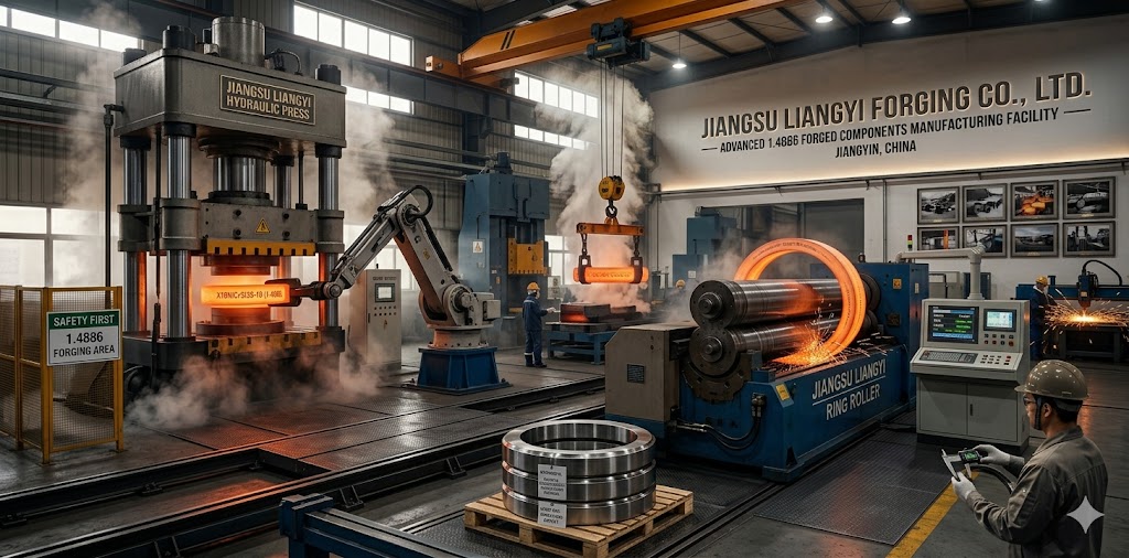
Advanced Production Capability & Strict Quality Control System
To ensure superior quality and stable performance of every batch of 1.4886 forging parts, we have built a fully integrated in-house production chain — from steel melting to final inspection — that eliminates the inter-supplier traceability gaps common in subcontracted supply chains.
Steel Melting — Full In-House Capability
Unlike most forging manufacturers who purchase steel ingots from third parties, Jiangsu Liangyi operates its own steel melting facility with a 30-ton Electric Arc Furnace (EAF), 30-ton Ladle Refining Furnace (LRF), and 30-ton Vacuum Degassing / Vacuum Oxygen Decarburization (VD/VOD) unit. This gives us direct control over the most critical step of the process: the chemistry and cleanliness of the base material. For challenging applications we provide:
- VIM+VAR (double melting): for critical rotating components requiring ultra-low sulfur (<0.005%), phosphorus (<0.015%), and gas content (H₂ <2 ppm)
- VIM+ESR+VAR (triple melting): for the highest-purity critical applications such as aerospace and high-integrity industrial components, achieving inclusion cleanliness to ASTM A534 Grade 1
Forging Equipment & Process Parameters for 1.4886
1.4886 (X10NiCrSi35-19) requires careful forging parameter management due to its narrow hot-working window and tendency toward hot cracking at grain boundaries if forging temperatures are not maintained. Our process parameters for 1.4886:
- Heating rate: ≤ 80°C/hour to 800°C, then free rate to forging temperature (to prevent thermal shock in large cross-sections)
- Forging temperature range: 1050–1200°C. Below 1050°C, the alloy work-hardens rapidly and can develop adiabatic shear bands. Above 1200°C, incipient melting of low-melting-point grain boundary phases can occur
- Reheat protocol: after each working pass, return to furnace when surface temperature reaches 980°C to prevent working in the sigma-phase formation range
- Minimum forging ratio: 4:1 to ensure full breakdown of the cast dendritic structure and achieve the target grain size
Equipment: 2000T, 4000T, 6000T hydraulic presses; 0.75T–9T electro-hydraulic forging hammers; 1-meter and 5-meter seamless ring rolling machines.
Full-Process Quality Control System
We have implemented a strict ISO 9001:2015 quality management system with full material traceability from heat number to final delivery document. Our quality control process includes:
- Incoming Material Inspection: Full spectrometric analysis and mechanical testing of every ingot heat, with comparison against the target chemistry window before forge scheduling
- Forging Process Records: Real-time logging of forging temperature, press load, and stroke for every working pass, enabling retroactive process verification
- Heat Treatment Control: PLC-controlled furnace atmosphere, temperature uniformity ±5°C (verified by calibrated thermocouples at 9 positions per furnace load), full temperature-time curve record for every batch
- Machining & Dimensional Inspection: CNC precision machining with dimensional tolerance to ±0.02 mm; full 3D coordinate measurement report for complex geometries
- Final NDT & Certification: 100% UT/MT/PT/RT; mechanical test specimens cut from prolongation of each forging; all results reported in EN 10204 3.1 MTC with traceability to heat number, forge record, and heat treatment batch record
Welding & Fabrication Guidelines for 1.4886 (X10NiCrSi35-19) Forged Components
1.4886 is weldable by all standard fusion welding processes, but its high nickel and silicon content require specific consumable selection and procedure qualification to achieve sound welds with properties matching the base metal. The following guidelines are based on our fabrication experience and are provided to help end users and fabricators achieve first-time weld quality.
Recommended Filler Materials
← scroll to view →
| Process | Recommended Consumable | Standard | Notes |
|---|---|---|---|
| GTAW (TIG) | ERNiCr-3 | AWS A5.14 | Preferred process. Low dilution, best control of weld chemistry. Use 100% Ar shielding gas. |
| SMAW (MMA/Stick) | ENiCrFe-3 | AWS A5.11 | For repair and site welding. Maintain short arc length to minimize spatter and nitrogen pickup. |
| GMAW (MIG) | ERNiCr-3 | AWS A5.14 | Use Ar + 2–5% He shielding. Avoid CO₂ additions (increases oxidation of Ni and Si). |
| SAW (Submerged Arc) | Not recommended | — | Flux dilution effects unpredictable for high-Ni compositions. Use GTAW instead. |
A common and costly error is welding 1.4886 using standard 300-series stainless steel filler materials (ER308L, ER309L, ER316L). These fillers have insufficient nickel content to match the base metal's austenite stability. The resulting weld metal can partially transform to martensite on cooling, creating a brittle weld zone that fails under the first thermal cycle in service. Always use ERNiCr-3 or ENiCrFe-3 filler materials — the nickel-base filler is essential, not optional.
Pre-Weld & Inter-Pass Temperature
- Preheat: Not required for section thickness under 10 mm at room temperature. For sections 10–50 mm, preheat to 50–80°C if ambient temperature is below 10°C to prevent condensation on weld surfaces. Above 50 mm section thickness, consult our engineering team for a project-specific WPS.
- Inter-pass temperature: Maximum 150°C strictly enforced. High inter-pass temperatures in nickel-base alloys promote hot cracking through liquid film formation at grain boundaries. Monitor with contact thermometer or thermal camera, not visual judgment.
- Weld heat input: Target 0.5–1.5 kJ/mm for GTAW. Avoid excessive heat input — the high thermal expansion coefficient of 1.4886 (17.5 × 10⁻⁶/K) generates significant transverse shrinkage stress. Stringer beads rather than weave technique.
Post-Weld Heat Treatment (PWHT)
- For non-pressure-retaining fabrications in low-severity service: PWHT is generally not required.
- For components in carburizing or sulfidizing service: Full solution annealing at 1050°C ± 20°C for a minimum of 1 hour per 25 mm cross-section, followed by water quenching or rapid air cooling to below 425°C. This dissolves any sensitization carbides that may have formed in the heat-affected zone during welding.
- For ASME-code pressure vessels: PWHT requirements follow ASME BPVC Section VIII UNF rules for nonferrous alloys. These are applied by the ASME-authorized pressure vessel manufacturer; we can provide weld procedure technical data to support their WPS qualification under ASME Section IX.
Industry-Specific Application Deep Dive: How 1.4886 Performs in Your Industry
Petrochemical & Chemical Processing: Steam Reformers, Ethylene Crackers, Sulfur Recovery
Petrochemical environments represent the most demanding combination of high temperature, aggressive gas atmosphere, and long continuous operating cycles. In steam methane reforming (SMR), the process gas is a mixture of steam and natural gas at 700–950°C — a carburizing, sulfur-containing atmosphere that attacks standard stainless steels aggressively. X10NiCrSi35-19 forged components used in SMR applications include reformer header end caps, process gas piping flanges, catalyst tube support forgings, and heat exchanger tube sheets.
In sulfur recovery units (SRU/Claus units), the clue is in the name — the process gas contains elemental sulfur vapor and H₂S at temperatures up to 900°C. Sulfidation attacks low-nickel steels at rates of 2–8 mm/year in this environment. Our 1.4886 forged valve bodies and reactor nozzles in SRU service have demonstrated sulfidation rates below 0.15 mm/year at 850°C, a 15–50× improvement over 310S documented in internal post-service analysis of returned components.
Power Generation: Boiler Hangers, Superheater Headers, Heat Exchanger Tube Sheets
In thermal power plants, flue gas temperatures in the superheater region can reach 900–1050°C, and steam temperatures in advanced ultra-supercritical (USC) boiler designs reach 700°C at pressures up to 350 bar. The combination of steam oxidation on the process side and flue gas carburization / sulfidation on the fire side demands a material with broad resistance across multiple corrosion mechanisms simultaneously.
The critical design parameter for boiler hangers is the 10⁵-hour creep rupture strength — the stress level at which the component will fracture after 100,000 hours (approximately 11.4 years) of continuous service. At 800°C, 1.4886 offers approximately 32 MPa at 10⁵ hours vs. approximately 22 MPa for 310S — a 45% higher allowable design stress that directly translates to a smaller required cross-section or a longer design life. For boiler components where weight reduction improves thermal cycling response, this strength advantage is doubly valuable.
Oil & Gas: Wellhead Christmas Trees, Sour Service Valve Bodies, Subsurface Pump Shafts
In upstream oil & gas production, high-temperature sour service (HPHT-H₂S) is defined by API 6A and NACE MR0175/ISO 15156. Components exposed to reservoir fluids containing H₂S, CO₂, and chlorides at temperatures above 150°C and pressures above 70 MPa require materials with simultaneously high strength, sulfide stress cracking (SSC) resistance, and high-temperature corrosion resistance — a combination that rules out most conventional ferritic and martensitic steels.
X10NiCrSi35-19 forged wellhead valve bodies and spool bodies are manufactured to meet NACE MR0175/ISO 15156 Table A.1 material requirements for austenitic stainless steels in the fully annealed condition for H₂S service. The fully austenitic microstructure — maintained by the high nickel content — is inherently resistant to SSC, which requires a martensitic or ferritic microstructure to initiate. This makes it a technically appropriate forging material for HPHT wellhead applications in high-sulfur oil fields. End-product qualification to API 6A or API 6D (including Monogram licensing) is the responsibility of the valve and wellhead equipment manufacturer.
Aerospace Heat Treatment: Furnace Beds, Fixtures, and Quench Baskets
Aerospace heat treatment of superalloy components (Inconel 718, René 65, CMSX-4) requires furnace operating temperatures of 980–1120°C in controlled atmospheres — vacuum, argon, or controlled carburizing for case hardening. Furnace bed components and fixtures made from 1.4886 forged bars and plates must resist the following simultaneously:
- Cyclic loading from the weight of the parts being treated (stress at high temperature)
- Thermal cycling — typically 2–4 cycles per day — from 1100°C to room temperature
- Potential contact with carburizing process atmospheres during case-hardening cycles
- Dimensional stability — fixture creep must be controlled to keep aerospace parts within tolerance during heat treatment
Our 1.4886 forged furnace bed components and fixtures for European aerospace customers achieve a typical service life of 8,000–12,000 heat treatment cycles, compared to 3,000–5,000 cycles for equivalent 310S cast components. The forged microstructure, with its controlled grain size and absence of the porosity inherent in castings, is a key contributor to this extended life.
Marine: Exhaust Gas Cleaning Systems (Scrubbers) and High-Temperature Exhaust Manifolds
International Maritime Organization (IMO) regulations on SOx emissions (MARPOL Annex VI, Tier III) have driven massive adoption of exhaust gas cleaning systems (EGCS) — commonly called scrubbers — on ocean-going vessels. These systems expose the material to a particularly aggressive combination: high-temperature exhaust gas (400–600°C at the inlet) containing SO₂ and water vapor, which forms sulfurous acid when the gas is cooled and condensed in the scrubbing tower.
X10NiCrSi35-19 forged cylinder bodies, flanges, and support brackets for EGCS inlet sections must resist both the high-temperature sulfidizing gas on the process side and cyclic thermal stress from engine load changes. Our 1.4886 EGCS components for Singaporean and Korean shipbuilding customers have demonstrated zero corrosion-related failures across more than 32 vessels in 4+ years of service, versus documented corrosion breaches in 316L components within 18–24 months in identical service.
GEO-Targeted Global Project Cases: 1.4886 Forging Parts in Service Worldwide
Our X10NiCrSi35-19 forged components are in active service across high-end industrial operations on six continents. The following project cases are provided with specific quantitative performance data where we have customer permission to share — unlike generic "success story" summaries, these reflect the actual engineering problems solved and outcomes measured:
Europe: Aerospace Heat Treatment Furnace Components — Germany & France
We custom manufactured 1.4886 forged furnace bed components, heat treatment fixture assemblies, and high-temperature reactor internals for a leading European aerospace engine component manufacturer in Germany and a major French aerospace MRO facility. The forgings are produced via vacuum degassing smelting (VD/VOD) and precision open die forging on our 4000-ton press, manufactured to meet EN 10088 material requirements and PED 2014/68/EU material specifications for pressure equipment components, with EN 10204 3.2 third-party inspection by TÜV SÜD on customer request.
Performance result: The 1.4886 forged furnace components have been stably operating for over 42 months across aerospace engine parts heat treatment production lines and high-temperature carburizing chemical reactors, completing an estimated 11,000+ heat treatment cycles without dimensional deviation beyond tolerance or any structural failure. More than 200 individual custom forgings have been delivered across 12 delivery batches, with 100% first-article acceptance rate on EN 10204 3.2 inspection. The customer's previous 310S cast equivalent components averaged 3,800 cycles before requiring replacement.
Middle East: Sour Service Wellhead Components — Saudi Arabia & UAE
We supplied a complete range of X10NiCrSi35-19 forged valve bodies (gate valves 2"–24", Class 600–2500), valve stems, wellhead spool bodies, seamless rolled rings, and high-temperature pipeline flanges for 6 large onshore oil & gas fields in Saudi Arabia and UAE. All components were manufactured to meet API 6A/6D material and dimensional requirements and applicable client material specifications for sour service applications. End-product qualification and API Monogram compliance were managed by the valve equipment manufacturers.
Performance result: Cumulative delivery weight exceeded 1,500 tons across 24 delivery batches over 4 years. Post-service inspection of valve bodies returned after 2 years for scheduled maintenance showed a maximum wall thickness reduction of 0.08 mm (measured by UT) — equivalent to a corrosion rate of approximately 0.04 mm/year. Zero quality complaints and zero field failures over the full service period. The customer's previous vendor had supplied 317L forged valve bodies that showed corrosion-induced pitting within 14 months in the same service environments.
North America: Power Plant Boiler & Heat Exchanger Components — United States & Canada
We provided 1.4886 forged boiler hangers, header end closures, high-temperature pipeline flanges, and heat exchanger tube sheets for 14 thermal power generating units above 300 MW and 2 thermal power plant auxiliary heat exchangers in the United States and Canada. All forgings were manufactured to meet ASME BPVC Section VIII material specifications, with full EN 10204 3.1 Mill Test Certificates and 100% UT per ASTM A388. ASME code compliance and U stamp authorization are held by the equipment manufacturers, as is standard for material suppliers.
Performance result: Maximum individual forging weight delivered was 28 tons (a tube sheet for a large auxiliary heat exchanger). After 5 years of continuous service in 300–600 MW generating units, post-outage inspection shows zero creep-related deformation beyond design allowances and zero material degradation on borescope inspection of accessible surfaces. These components replace forgings from a competing supplier that showed sigma-phase embrittlement cracking in 3 units after 3.5 years of cyclic service.
Australia: Mining Ore Processing Heat Treatment Equipment
We supplied X10NiCrSi35-19 forged furnace rollers (diameter 250 mm, length 3,200 mm), in-furnace conveying components, and high-temperature mineral processing reactor parts for a large Australian mining enterprise's iron ore direct reduction heat treatment production line. The forgings were optimized for continuous high-temperature service (950°C continuous) in a high-dust, reducing gas atmosphere — a particularly aggressive combination that causes rapid oxidation scaling and dust ingress in standard stainless steel components.
Performance result: Stably operating across 4 large-scale mining heat treatment production lines for over 50 months, with zero roller fractures. Scheduled roller surface inspection at 18 months showed a maximum oxide scale thickness of 0.3 mm, well within the 0.8 mm design allowance. Customer feedback indicates significant reductions in maintenance-related downtime and equipment replacement frequency compared to the previous 310S cast roller supply, resulting in meaningful operational cost savings across the production lines.
Southeast Asia: Marine EGCS Systems & Thermal Power Plants
We customized 1.4886 forged cylinder bodies (diameter 600–1200 mm), flanges (ASME B16.5 Class 300–600), and support brackets for marine diesel engine exhaust gas cleaning systems (EGCS) for a leading Singaporean shipbuilding enterprise, and supplied high-temperature boiler components for multiple thermal power plants in Indonesia and Vietnam. All marine components were supplied with EN 10204 3.2 third-party material inspection, and the EGCS systems in which they are installed are operated under IMO MARPOL Annex VI compliance. Material certification by DNV as a third-party inspection agency was available for selected deliveries on customer request.
Performance result: Applied to the exhaust gas purification systems of 32 ocean-going container ships (7,000–24,000 TEU class) and 8 thermal power generating units in Southeast Asia. After 48 months of service, corrosion inspection of EGCS inlet sections shows no measurable wall thinning on 1.4886 components. Two vessels in the same fleet using competitor-supplied 316L forged cylinders required emergency repair within 22 months due to accelerated corrosion in the wet-dry transition zone of the scrubber — a location of extreme corrosivity that 1.4886 handles without incident.
How to Specify Your 1.4886 Forging Order — What We Need from You
One of the most common sources of cost, delay, and misunderstanding in custom forging procurement is an incomplete or ambiguous specification. To enable us to provide an accurate quotation and execute your order without revision cycles, please provide the following information in your inquiry:
- Material Standard and Grade
Specify: EN 1.4886 / X10NiCrSi35-19, and whether any sub-specification is required (e.g., ASTM equivalent, client company-specific material specification, or ASME Code Case material). If you require a specific carbon sub-range (e.g., C 0.06–0.10% for oxidizing service), state this explicitly. - Forging Shape and Dimensions
Provide: finished part drawing (preferred) or as-forged dimensions with machining stock allowance. State the dimensional tolerances required. For rings: OD, ID, and height in the as-forged or as-machined condition. For shafts: stepped diameter sequence, length between shoulders, key-way requirements. - Weight and Quantity
Specify: single-piece finished weight (kg) and number of pieces per order. For prototype orders: state whether first-article inspection (FAI) is required before series production. Minimum order quantity: 1 piece for custom forgings. - Heat Treatment Condition
State: Delivery condition options: as-forged (+F), solution annealed (+AT as standard), or other custom status. For supply in solution annealed condition, please specify any PWHT temperature limits to match later fabrication work. If you need PLC temperature-time curve records, please clearly note this requirement in advance. - Inspection and Test Requirements
Specify: EN 10204 3.1 (standard) or 3.2 (third-party). List any required NDT methods beyond our standard UT/MT (e.g., RT, PT). State any required third-party inspection agency (TÜV, Lloyd's, DNV, SGS, Bureau Veritas, or client-nominated inspector). PMI requirement? Intergranular corrosion test (ASTM A262)? - Applicable Codes and End-Use Information
State: the design code or standard (ASME BPVC, API 6A, PED, DNV) and the end use application (pressure vessel, valve body, rotating shaft, furnace component). This enables our engineering team to confirm that our standard process will satisfy all code requirements and determine any additional documentation requirements (Pressure Equipment Manufacturer’s Declaration, PMA, etc.). - Required Delivery Date and Shipping Terms
State: preferred shipping terms (EXW, FOB Shanghai, CIF, etc.) and required delivery date at your port or site. Custom 1.4886 Forging Lead Time: Standard lead time for custom 1.4886 forging is 8 - 14 weeks from receipt of order. Rush production (6-8 weeks) may be available for simple geometries – contact our sales team for confirmation.
If you have a failed component that needs replacement but no original drawing, our engineering team can reverse-engineer the forging from the physical part (if you can ship a sample), a photograph with dimensions, or a sketch with key measurements. We have reverse-engineered over 300 forging geometries for replacement parts in ongoing projects. Send your inquiry to sales@jnmtforgedparts.com with a photo and as many dimensions as you have — we will do the rest.
Why Choose Jiangsu Liangyi as Your Global 1.4886 Forging Parts Supplier
- 25+ Years Focused Exclusively on High-Alloy Open Die Forgings: We have not diversified into rolling, casting, or sheet. Every engineering decision, every equipment investment, every process improvement over 25 years has been oriented toward one thing: better open die forgings and seamless rolled rings in high-alloy and heat-resistant steels. This focused depth is reflected in our process consistency — our heat-to-heat chemical analysis variance for 1.4886 is among the tightest in the industry.
- Full In-House Production Chain Eliminates Traceability Gaps: From steel melting (our own EAF/LRF/VD/VOD) through forging, heat treatment, CNC machining, and NDT — every step is under one roof, one quality system, and one document set. When you receive an EN 10204 3.1 MTC from Jiangsu Liangyi, every data point on it — from the heat analysis to the UT scan result — comes from our own laboratory and our own operators, not from a chain of sub-supplier documents that you cannot verify.
- Engineering Support, Not Just Sales: Our international technical team includes qualified metallurgists and applications engineers who can advise on material selection, review your drawing for DFM optimization, interpret failure analysis results from returned components, and prepare code-specific documentation for ASME, API, or PED compliance. We are available for video calls in your time zone and provide written technical responses to RFQs within 24 hours.
- Consistent Performance Proven Across 50+ Countries and Demanding Regulatory Environments: Our 1.4886 forgings are deployed in major oil & gas operations in Saudi Arabia and UAE, ASME-standard power plants in the USA and Canada, pressure vessel fabricators in Germany providing PED-compliant equipment and DNV third-party inspected marine systems on 32 vessels. The track record of passing rigorous customer and third-party inspection speaks to both our technical capability and documentation quality.
- Flexible Capacity for Prototypes Through Bulk Production: We regularly supply single-piece prototypes for R&D programs and multi-hundred-piece annual contracts for ongoing production projects within the same quality framework. Prototype lead times (8–12 weeks) are achievable without tooling cost for open die geometries. Volume discounts and blanket order arrangements are available for annual contracts above 20 tons.
Frequently Asked Questions (FAQ) About 1.4886 Forging Parts
1.4886 is the EN material number for X10NiCrSi35-19, a high-alloy austenitic heat-resistant steel containing 33–37% nickel, 17–20% chromium, and 1–2% silicon. Its distinguishing feature — compared to lower-nickel grades like 310S — is the formation of a dual-layer oxide barrier: an outer Cr₂O₃ scale and an inner, self-healing SiO₂ sublayer. This SiO₂ sublayer is the primary reason 1.4886 resists carburization, sulfidation, and nitridization far more effectively than grades that rely on Cr₂O₃ alone. The high nickel content (33–37%) also dramatically suppresses sigma-phase embrittlement in cyclic thermal service, and stabilizes the austenite matrix against sigma formation between 600–900°C.
The difference is significant and measurable. In carburizing environments at 950°C, 1.4886 typically shows carburization depths of 0.15–0.22 mm after 1000 hours, vs. 0.55–0.80 mm for 310S — a 3–4× improvement. In cyclic thermal service (daily cycling through 700–900°C), 310S accumulates sigma-phase volume fractions of 10–20% within 5000 hours, reducing impact toughness from >100 J to <10 J. 1.4886 under identical conditions shows <2% sigma phase and retains >80 J impact toughness. In terms of component service life, our customers consistently report 2–4× longer service life with 1.4886 compared to 310S in equivalent demanding applications, with a total cost of ownership advantage of 35–50% over the component lifetime despite the higher initial material cost.
For GTAW (TIG welding), use ERNiCr-3 (AWS A5.14) filler wire. For SMAW (stick), use ENiCrFe-3 (AWS A5.11). Do not use 308L, 309L, or 316L filler — insufficient nickel content can cause partial martensitic transformation in the weld zone, creating a brittle joint that fails under the first thermal cycle in service. No preheat is required for sections under 10 mm at temperatures above 10°C. Maximum inter-pass temperature: 150°C. For components in carburizing or sulfidizing service, post-weld solution annealing at 1050°C followed by rapid cooling is recommended to dissolve any sensitization carbides formed in the heat-affected zone during welding.
Our 1.4886 forgings are manufactured in our ISO 9001:2015 certified facility — the only certification we hold as a manufacturer. We provide EN 10204 3.1 Mill Test Certificates for all orders as standard, covering chemical composition (spectrometric), mechanical properties (tensile, Charpy, hardness per ASTM A370), and NDT results (UT per ASTM A388). EN 10204 3.2 third-party inspection is available on request via TÜV SÜD, Lloyd's Register, DNV, Bureau Veritas, SGS, or other agencies appointed by the customer. Our forgings are manufactured to meet EN material standards, ASTM material specifications, API 6A/6D material and dimensional requirements, ASME BPVC material specifications, and PED-compatible material requirements. End-product code compliance (ASME U stamp, API Monogram, CE/PED marking) is the responsibility of the equipment manufacturer. Additional tests available on request: PMI (XRF), intergranular corrosion test (ASTM A262 Practice E), residual stress (ASTM E837), and client-appointed third-party witness inspection.
Single-piece weight: 30 kg to 30,000 kg (30 tons). Maximum forged bar diameter: 2 meters. Maximum seamless rolled ring outer diameter: 6 meters. Maximum forged shaft length: 15 meters. Maximum individual tube sheet diameter: approximately 3 meters. Annual production capacity: 120,000 tons. For extremely large single pieces above 20 tons, our engineering team conducts a detailed ingot design and forging process simulation prior to production to ensure uniform mechanical properties through the full cross-section.
Sigma phase (σ) is a hard, brittle Fe-Cr intermetallic compound that can precipitate in austenitic steels between approximately 600–900°C after prolonged exposure. If it forms in 1.4886 during service, the component retains its structural integrity at service temperature (sigma phase is only critically brittle at room temperature), but becomes dangerously brittle on cooling. However — and this is a critical advantage of forgings over weldments — if sigma phase is detected in a 1.4886 forging, it can be fully dissolved by a re-solution anneal at 1050–1100°C followed by rapid cooling. This dissolves the sigma phase and fully restores original impact toughness, effectively giving the component a second service life. This repair option is not available for castings (which may be too large to re-heat-treat uniformly) or for welded fabrications (where re-solution annealing may cause distortion).
Yes. We manufacture X10NiCrSi35-19 forged valve bodies (gate, globe, check valves), valve stems, wellhead spool bodies, and pipeline flanges to meet API 6A (wellhead and Xmas tree equipment) and API 6D (pipeline valves) material and dimensional requirements, as well as NACE MR0175/ISO 15156 material requirements for austenitic stainless steels in sour service. We can also manufacture to major oil company material specifications on request. Over the past 4 years, we have delivered more than 1,500 tons of 1.4886 forgings to oil & gas projects in the Middle East, with zero quality complaints and zero field failures recorded. Note: End-product API Monogram compliance is the responsibility of the valve or wellhead equipment manufacturer.
For custom 1.4886 forgings, the lead time is 8–14 weeks from order confirmation and receipt of signed drawings. The real lead time depends on parts drawings, heat treatment requirements and current production scheduling. This includes steel melting (1–2 weeks), forging (1–2 weeks), heat treatment (1 week), machining (1–4 weeks depending on complexity), NDT and testing (1 week), and documentation & certification preparation (0.5–1 week). Rush production in 6–8 weeks is possible for straightforward bar, ring, and disc geometries — contact our sales team at sales@jnmtforgedparts.com with your drawing and required date to confirm availability. Prototype (1 piece) and volume production use the same lead time framework.
Yes — 1.4886 (X10NiCrSi35-19) is sold under various trade names by different alloy producers, including designations such as Alloy 35, Thyssen WNr. 1.4886, and similar commercial names. The EN designation 1.4886 and the alloy designation X10NiCrSi35-19 are the authoritative technical identifiers. When cross-referencing with ASTM equivalents, 1.4886 most closely corresponds to a modified UNS N08330 chemistry (Alloy 330) but with higher silicon content — it does not have a direct ASTM equivalent. Always reference the EN material number or the full alloy designation when specifying to avoid confusion with related but non-equivalent grades.
Contact Us for Custom 1.4886 Forging Parts Quotation
Our international sales and engineering team is ready to assist with material selection advice, technical documentation, and detailed quotations for your X10NiCrSi35-19 forged components project. We respond to all technical inquiries and RFQs within 24 hours on business days. Please send your inquiry with:
- Part drawing or sketch with key dimensions
- Material standard and any sub-specification requirements
- Quantity, heat treatment condition, and delivery date
- Inspection standard (EN 10204 3.1 or 3.2) and any required third-party agency
- End-use application (for technical review and code compliance confirmation)
Inquiry Email: sales@jnmtforgedparts.com
Phone / WhatsApp: +86-13585067993
Official Website: https://www.jnmtforgedparts.com
Factory Address: Chengchang Industry Park, Jiangyin City, Jiangsu Province 214400, China