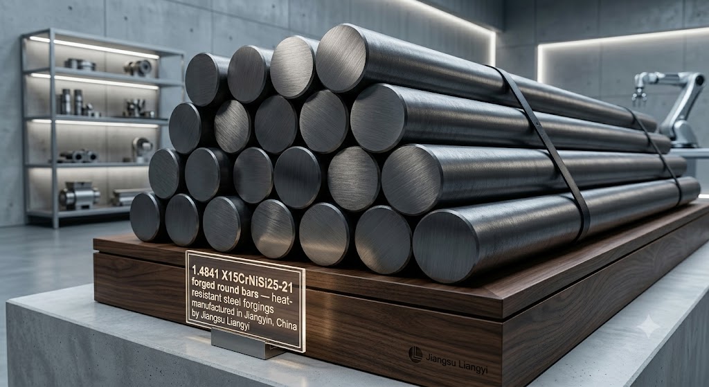
1.4841 (X15CrNiSi25-21) Forging Parts
China Jiangyin Professional Manufacturer
Jiangsu Liangyi is a specialist manufacturer of 1.4841 (X15CrNiSi25-21) open die forgings and seamless rolled rings, operating from Jiangyin, Jiangsu Province — one of China's most concentrated forging and metallurgical manufacturing clusters. Since our founding, we have built over 25 years of hands-on experience producing custom heat-resistant steel forgings for the world's most demanding thermal environments. Every 1.4841 component we ship carries the full metallurgical traceability that global OEMs and EPC contractors require.
This page goes beyond a standard product listing. We share the engineering reasoning behind 1.4841's alloy design, the exact process controls we use in forging, and the practical guidance our engineers provide to buyers selecting materials for extreme-temperature service. If you are an engineer, procurement specialist, or quality auditor, the depth here is intended for you.
Strategic Location: Jiangyin, Jiangsu Province, China
Our factory is located at Chengchang Industry Park, Jiangyin City, Jiangsu Province, China (ZIP 214400) — just 120 km west of Shanghai Port, the world's highest-volume container port. This position inside the Yangtze River Delta industrial corridor gives us direct access to Jiangsu province's network of raw material producers, precision tooling suppliers, and heat treatment specialists. Jiangyin itself hosts over 80 metallurgical companies, meaning supply chain disruptions that would halt factories elsewhere rarely affect our delivery schedule.
📞 Phone / WhatsApp: +86-13585067993 | ✉️ Email: sales@jnmtforgedparts.com
Why Engineers Choose 1.4841 (X15CrNiSi25-21) for High-Temperature Forgings
When component designers are working in the 900°C–1100°C temperature range, they face a fundamental materials gap. Standard austenitic stainless steels such as 316L or even 310S are either too weak at those temperatures or form unstable oxide scales that spall rapidly, exposing fresh metal to further attack. At the upper end, nickel-based superalloys provide excellent performance but at a price premium — sometimes 10 to 20 times higher — that is economically prohibitive for large structural components like valve bodies, pump casings, or reactor nozzles.
1.4841 (X15CrNiSi25-21) was specifically engineered to fill this gap. Its alloy design — high chromium (24–26%), moderate nickel (19–22%), elevated silicon (1.5–2.5%), and a deliberate allowance of carbon up to 0.20% — creates a material that delivers reliable oxidation resistance up to 1100°C in continuous service, acceptable creep strength at 800°C, and a procurement cost that makes it viable for heavy industrial components. This is why it appears in European standard EN 10095 as a dedicated heat-resistant grade rather than simply an elevated-temperature variant of a corrosion-resistant stainless.
💡 Engineer's Perspective
Many buyers first enquire about 310S (1.4845) because it is more widely specified in older plant standards. Our technical team regularly helps engineers review whether 310S is truly optimal for their conditions. In applications involving intermittent heating, thermal cycling, or environments with slightly elevated sulfur or carbon activity, 1.4841's higher silicon content and higher carbon-allowed microstructure often deliver measurably longer service intervals. We provide side-by-side oxidation and creep data on request.
The Metallurgical Role of Silicon in 1.4841: Why It Matters for Forgings
Most technical data sheets for heat-resistant stainless steels list silicon content without explaining why it matters. For X15CrNiSi25-21, silicon is not merely a residual deoxidation element — it is a functionally critical alloying addition that fundamentally changes oxidation behavior at elevated temperatures.
How the Duplex Oxide Scale Forms
When 1.4841 steel is exposed to high-temperature oxidizing atmospheres, two protective oxide layers develop simultaneously. The outer layer consists primarily of chromia (Cr₂O₃), which forms rapidly from the high chromium content and acts as the main diffusion barrier against oxygen ingress. Beneath this chromia layer, the elevated silicon content drives the formation of a secondary silica-rich (SiO₂) sub-scale at the metal-oxide interface. This SiO₂ layer is extraordinarily dense and acts as an additional barrier that dramatically slows the inward diffusion of oxygen and outward diffusion of metal cations.
The practical result of this duplex Cr₂O₃/SiO₂ architecture is that 1.4841 consumes base metal at a significantly lower rate than alloys with comparable chromium but without the silicon boost. In cyclic oxidation tests conducted at 1000°C in air with 15-minute cycles, silicon-containing heat-resistant steels of this class consistently show lower total mass change and better scale adhesion than their low-silicon counterparts. This is the core reason why furnace engineers who have experienced scale spallation problems with 309S or lower-grade alloys find that switching to 1.4841 extends the service life of their components.
Silicon's Influence on the Forging Process
From a forging process perspective, silicon has important secondary effects that experienced forge shops must manage. Silicon increases the deformation resistance of austenite at forging temperatures, which means 1.4841 requires higher press forces than 304 or 316 grade steels of the same cross-section. In our facility, we calculate forging loads using modified Siebel equations that account for the elevated silicon content and its effect on hot flow stress. This is one reason why not all forging companies can produce large 1.4841 components reliably — presses that are rated for standard austenitic grades may be working at the edge of their capacity on 1.4841 heavy sections.
Silicon also narrows the optimal forging temperature window. The hot ductility trough — the temperature range where the alloy is prone to hot tearing — is slightly elevated compared to lower-silicon austenitic grades. Our process parameters place the finishing temperature above 1050°C to avoid finishing in the ductility trough, a discipline that requires precise pyrometry on every heat and real-time temperature feedback to the press operator. Components forged below this threshold by suppliers without strict process controls may exhibit surface cracking that only becomes visible after machining or NDT.
💡 What This Means When Sourcing Forgings
When evaluating 1.4841 forging suppliers, ask specifically about their temperature monitoring protocol during forging and their re-heating procedure for large components that cool between passes. A supplier who cannot answer these questions precisely has likely not engineered their process specifically for this alloy. We document forging temperature logs for every heat and make them available as part of our quality package.
1.4841 Forged Product Shapes & Dimensional Capabilities
We manufacture the full spectrum of open die forged and ring-rolled shapes in 1.4841 (X15CrNiSi25-21). The dimensional ranges below reflect our current installed equipment — if your requirement falls outside a listed range, contact us; in many cases we can combine forging steps or subcontract specific operations within our partner network while maintaining full traceability.
Forged Bars, Shafts, and Rods
- Round bars: Diameter 60 mm to 2,000 mm, length up to 6,000 mm per piece (longer available in sections)
- Square and rectangular bars: Custom cross-sections, minimum 50 mm side, maximum ~800 × 800 mm
- Stepped shafts and gear shafts: Multi-diameter profiles up to 15 m total length, individual step ratios up to 3:1 in a single forging pass
- Splined drive shafts: Forged near-net-shape blanks for downhole drilling, pump, and turbine applications; spline geometry rough-machined in-house before final machining by customer
- Flat bars and slab sections: Width up to 1,600 mm, thickness from 30 mm, suitable for baffle blanks and structural fabrications
Seamless Rolled Rings
- Plain rings: OD from 200 mm to 6,000 mm; height from 30 mm to 2,000 mm; wall thickness from 20 mm
- Contoured (profiled) rings: T-section, L-section, and custom cross-sections rolled to near-net shape — reduces machining time significantly on complex valve seat rings and gear rings
- Gear ring blanks: Ring-rolled to OD tolerance ±3 mm before gear hobbing; grain flow orientation optimized for tooth root fatigue resistance
- Pressure vessel flanged rings: Heavy-wall rings with integral flange, replaces weld assemblies in high-temperature reactor applications
- Maximum single ring weight: 30 tons finished weight
Hollow Components: Hubs, Sleeves, Shells, and Cylinders
- Forged and bored hollow bars: OD up to 3,000 mm, minimum wall thickness achievable approximately 50 mm depending on diameter
- Pump casings and compressor barrels: Complex hollow forgings machined to pressure-retaining wall thickness; full UT inspection per EN 10228-3 level 3 or 4
- Sleeve and bushing blanks: Short L/D ratio hollow sections for bearing housings, seal chambers and lined piping components
- Reactor pressure shells: Heavy-wall cylinders with integral nozzle stubs forged in a single heat, deleting longitudinal welds that are a chronic reliability concern in welded fabrications
Disks, Blocks, Plates, and Tube Sheets
- Round disks and plate blanks: Diameter up to 3,500 mm, thickness from 20 mm to 1,000 mm
- Tube sheets: Forged plate quality is dramatically superior to rolled plate for tube sheet applications — the through-thickness mechanical properties and absence of laminar defects guarantee tube-to-tubesheet joints hold integrity under thermal cycling
- Baffle plates and nozzle blanks: Supply in rough-machined condition with surface finish Ra ≤6.3 μm, ready for drilling
- Flange blanks: Rough-bored, faced, and marked with heat number before dispatch; EN 10204 Type 3.1/3.2 MTC supplied to support European PED traceability requirements (CE marking of the assembled pressure equipment is the responsibility of the equipment manufacturer)
Forged Pipes and High-Pressure Tubings
- Thick-wall forged tubes: OD 60 mm to 600 mm, wall thickness 15 mm and above; suitable for high-pressure steam lines, process heater coil connections, and reformer piping
- Seamless forged tube blanks: Bored and honed bore finish Ra ≤3.2 μm for important flow applications
- Pipe fittings and elbows: Forged and machined elbows, tees, and reducers to ASME B16.11 or EN 10253 dimensions
1.4841 Forging Applications by Industry — Engineering Context
Understanding why 1.4841 is specified in each application helps engineers make better design decisions and procurement teams ask better questions. We cover the main industries below with engineering context that goes beyond a simple list.
Valve Industry: Where Scale Adhesion Is Everything
Valve components exposed to high-temperature process fluids face a specific failure mechanism that often surprises plant engineers: oxide scale that forms on internal surfaces spalls under thermal cycling, generating hard ceramic particles that score soft seats, wedge between disc and seat faces, and cause valve leakage — the primary cause of unplanned downtime in high-temperature process plants. The duplex Cr₂O₃/SiO₂ scale formed by 1.4841 is significantly more adherent than the scale on standard austenitic steels because the SiO₂ sub-scale acts as a mechanical anchor and its lower thermal expansion coefficient (relative to the steel substrate) means it spalls less readily during cooling cycles.
- Valve balls, bonnets, bodies, and stems for gate, globe, and ball valves in service above 600°C
- Seat rings and closure discs for high-temperature throttling service where seat material hardness must be maintained
- Butterfly valve shafts: the forged shaft must maintain its dimensional stability under continuous torsional load at temperature — 1.4841's elevated proof strength at 700°C–800°C is decisive here versus lower-alloyed grades
- Ultrasonic flowmeter bodies and venturi meter tube sections where bore geometry must be held within tight tolerance throughout service life
- High-pressure safety relief valve bodies for petrochemical service: ASME VIII Division 1 or EN 13445 calculations are supported by our engineering team
Oil and Gas Wellhead and Downhole: Pressure + Temperature Combined
The HTHP (High Temperature High Pressure) sector pushes materials to their combined thermomechanical limits. Wellhead components at depths exceeding 4,000 m may see bottomhole temperatures above 200°C combined with wellhead pressures exceeding 15,000 psi (103 MPa). While 1.4841 is selected here primarily for its corrosion resistance against H₂S-bearing brines and its non-magnetic properties (critical for directional drilling measurement tools), its superior forged grain structure is what delivers the impact toughness and pressure-retaining reliability required under API 6A certification.
- Christmas trees (wellhead equipment), casing heads, and tubing heads — all forged single-piece, avoiding the weld heat-affected zones that are initiation sites for stress corrosion cracking
- ESP (Electric Submersible Pump) motor shaft and housing forgings for geothermal wells exceeding 180°C bottomhole temperature
- Mud motor rotor housings and splined drive shafts for directional drilling tools — forged grain alignment along the shaft axis maximizes fatigue life under torsional-bending combined loading
- Subsea tree connector bodies and mandrel hubs — complete heat-number-level material traceability and third-party inspection documentation available to support customer API qualification packages
Power Generation and Nuclear: The Most Demanding Qualification Chain
Power generation applications — particularly nuclear — impose the most exacting qualification requirements in the forging industry. Components must pass seismic qualification, leak-before-break fracture mechanics analysis, and in some jurisdictions, surveillance testing extending 40+ years into service. Our experience supplying nuclear-grade forgings has shaped our process discipline across the entire facility.
- Primary coolant pump casings and seal chamber housings: ESR (Electroslag Remelted) quality steel available, with grain size verified to ASTM 5–7 and Charpy impact energy ≥60 J at 20°C; full material documentation supplied to customer's nuclear procurement specification
- Turbine compressor impeller blanks for combined-cycle power plants: forging reduction ratio documented per EN 10243 or ASME SA-788 as required by customer purchase order
- Pressure vessel nozzle forgings for heat recovery steam generators (HRSG): NDE performed and documented per applicable standard stated in customer specification
- Boiler superheater header forgings and transition cones for ultra-supercritical steam conditions (≥600°C steam temperature)
Chemical and Petrochemical Reactors: Long Cycles, Corrosive Environments
Ethylene crackers, ammonia reformers, and hydrogen production plants run at temperatures between 850°C and 1050°C for continuous campaigns sometimes lasting 3–5 years before a scheduled turnaround. Material loss from oxidation and carburization in these environments is a real cost that engineers track carefully. Our 1.4841 forgings are specified for these applications because the elevated silicon content provides meaningful resistance to both carburization (carbon uptake from cracking atmosphere) and coking (carbon deposition), which together degrade lower-silicon alloys significantly faster.
- Reformer tube manifold forgings and header nozzles
- Hydrocracker and hydrotreater reactor nozzles and manway forgings: hydrogen embrittlement resistance validated by Nelson curve position for 1.4841 chemistry
- Sulfur recovery unit (SRU) component forgings: Claus process gases contain SO₂ and H₂S in combinations that attack iron-based alloys aggressively; 1.4841's high Cr-Ni balance provides acceptable resistance in the 250°C–450°C Claus converter range
- Ethylene cracker transfer line exchanger (TLE) flanges and nozzles
Pump and Compressor Industry: Balancing Strength and Corrosion
Centrifugal pumps handling hot process fluids at 400°C–650°C require casing and impeller materials that maintain dimensional stability under pressure while resisting corrosive attack. The challenge is that many candidate alloys with adequate corrosion resistance lack the elevated-temperature proof strength to contain the operating pressure without excessive wall thickness. 1.4841's minimum 0.2% proof strength of 230 MPa at room temperature translates to approximately 140–160 MPa at 650°C — sufficient for most process pump pressure ratings without requiring excessively heavy-section castings or weld-buildup repairs.
- Pump casing halves, discharge nozzles, and suction covers — forged as separate components and machined to a matched assembly
- Impeller hub forgings: ring-rolled blanks provide circumferential grain orientation that resists the centrifugal hoop stress mechanism responsible for disk burst failures in high-speed pumps
- Wear ring forgings: tight tolerancing on bore and OD achievable to h6/H7 in forged condition before grinding
- Compressor stage discs and diaphragm forgings for high-temperature gas compression stages
Heat Exchanger and Furnace Equipment: Managing Thermal Cycles
- Tube sheet forgings for fired heaters and process gas coolers: the superior through-thickness properties of a forged tube sheet (compared to rolled plate) prevent the ligament cracking failures that occur after repeated thermal cycles in welded-plate tube sheets
- Furnace radiant tube return bends and manifolds — components that see the highest furnace temperature and must maintain adequate creep strength to avoid deformation that would contact adjacent components
- Industrial furnace door frames and burner blocks: 1.4841's non-scaling surface at 1000°C+ means the component retains its original geometry without the progressive surface loss (≥0.5 mm/year in some lower-grade alloys) that eventually compromises sealing
- Heat exchanger floating head covers and baffle support rings
1.4841 (X15CrNiSi25-21) Complete Material Properties
The following data reflects the standard specification under EN 10095 in the solution-annealed (+AT) condition. When ordering forgings, always confirm whether properties apply to the forging as a whole (bulk test) or are quoted from a specifically located test coupon (which may show higher values due to higher forging reduction in that zone). Our MTCs clearly identify test location and forging reduction ratio.
Chemical Composition (EN 10095 Requirements)
| Element | Min (%) | Max (%) | Role in Alloy Design |
|---|---|---|---|
| Carbon (C) | — | 0.20 | Provides solid solution strengthening and elevated-temperature creep resistance; controlled upper limit prevents sensitization risk during slow cooling |
| Silicon (Si) | 1.50 | 2.50 | Forms SiO₂ sub-scale for superior oxidation resistance; increases hot deformation resistance |
| Manganese (Mn) | — | 2.00 | Austenite stabilizer; controls sulfide morphology |
| Phosphorus (P) | — | 0.045 | Residual; controlled to minimize temper embrittlement |
| Sulfur (S) | — | 0.015 | Controlled low to improve hot ductility and transverse toughness in forgings |
| Chromium (Cr) | 24.00 | 26.00 | Primary oxidation resistance element; forms Cr₂O₃ protective scale |
| Nickel (Ni) | 19.00 | 22.00 | Austenite stabilizer; improves ductility, toughness, and carburization resistance |
| Nitrogen (N) | — | 0.11 | Mild solid solution strengthener; controlled to avoid porosity during solidification |
| Iron (Fe) | Balance | Matrix element | |
Mechanical Properties (Solution Annealed, +AT)
| Property | Symbol | Minimum Value | Typical Achieved (Jiangsu Liangyi Forgings) |
|---|---|---|---|
| Tensile Strength | Rm | 550 MPa | 600–720 MPa |
| 0.2% Proof Strength | Rp0.2 | 230 MPa | 260–320 MPa |
| Elongation at Fracture | A | 28% | 32–42% |
| Reduction of Area | Z | — | 55–70% |
| Brinell Hardness | HB | — | 150–210 HB (max 223 HB) |
| Charpy Impact Energy (KV at 20°C) | KV | — | ≥100 J (typical 120–180 J) |
Physical Properties
| Property | Value | Condition / Temperature |
|---|---|---|
| Density | 7.90 g/cm³ | 20°C |
| Modulus of Elasticity (E) | 200 GPa | 20°C |
| Modulus of Elasticity (E) | 155 GPa | 800°C |
| Thermal Conductivity | 15 W/(m·K) | 20°C |
| Thermal Conductivity | 21 W/(m·K) | 800°C |
| Thermal Expansion Coefficient (20–800°C) | 17.5 × 10⁻⁶ /K | Mean value |
| Specific Heat Capacity | 500 J/(kg·K) | 20°C |
| Electrical Resistivity | 0.82 μΩ·m | 20°C |
| Magnetic Permeability | <1.05 μᵣ | Annealed condition |
1.4841 High-Temperature Mechanical Performance in Depth
The following data explains how 1.4841 actually performs across the temperature range relevant to its applications. This is information that goes beyond most supplier data sheets and is essential for engineering calculations.
Elevated-Temperature Proof Strength and Tensile Strength
| Temperature | Rp0.2 (MPa) — approx. | Rm (MPa) — approx. | Elongation A (%) |
|---|---|---|---|
| 20°C | 230–320 | 600–720 | 32–42 |
| 200°C | 165–220 | 510–620 | 34–44 |
| 400°C | 140–190 | 450–560 | 36–46 |
| 600°C | 120–165 | 370–470 | 38–50 |
| 700°C | 100–140 | 280–370 | 40–55 |
| 800°C | 80–110 | 200–270 | 42–60 |
| 900°C | 55–75 | 120–160 | 45–65 |
| 1000°C | 30–45 | 70–95 | 50–70 |
Note: Values above are approximate references based on EN 10095 and published data for this alloy class. Actual forging test values should be confirmed by MTC for each specific order. Our forgings consistently meet or exceed the minimum values shown in Column 2.
Creep Rupture Strength
Creep — the slow plastic deformation that occurs under sustained stress at elevated temperature — is the dominant failure mechanism for high-temperature structural forgings. For pressure-retaining components designed to API, EN 13445, or ASME VIII standards, creep rupture strength values over 100,000 hours (approximately 11.4 years) are used to set allowable stresses.
| Temperature | Rupture Stress at 10,000 h (MPa) | Rupture Stress at 100,000 h (MPa) |
|---|---|---|
| 700°C | ~110 | ~65 |
| 800°C | ~65 | ~35 |
| 900°C | ~30 | ~15 |
| 1000°C | ~10 | ~5 |
Thermal Cycling Behaviour: A Key Differentiator
Static oxidation data tells only part of the story. Equipment that undergoes planned or unplanned shutdowns — furnaces, reformers, process heaters — subjects components to repeated thermal cycles between ambient and operating temperature. Each cycle creates thermal fatigue strain in the oxide scale due to the mismatch in thermal expansion coefficients between the scale and the substrate metal. When scale spalls, fresh metal surface is exposed and oxidation accelerates.
In comparative cyclic oxidation testing at 1000°C (heating for 1 hour, forced-air cooling for 10 minutes, 500 total cycles), 1.4841-class alloys demonstrate significantly better mass retention than X15CrNiSi20-12 (1.4828 / 309S) alloys of comparable weight. The SiO₂ anchoring mechanism described earlier plays a critical role: by "pinning" the chromia scale at the metal surface, silicon reduces the delamination tendency that causes progressive metal loss in lower-silicon grades.
1.4841 vs Other Heat-Resistant Steel Grades: Detailed Comparison
| Property | 1.4841 (X15CrNiSi25-21) | 1.4845 / 310S (X6CrNi25-20) | 1.4828 / 309S (X15CrNiSi20-12) | 1.4878 (321H) | 1.4404 / 316L |
|---|---|---|---|---|---|
| EN Material No. | 1.4841 | 1.4845 | 1.4828 | 1.4878 | 1.4404 |
| Max Continuous Temp. | 1100°C | 1150°C | 1050°C | 900°C | 850°C |
| Silicon Content | 1.5–2.5% | ≤0.75% | 1.5–2.5% | ≤0.75% | ≤1.0% |
| Chromium Content | 24–26% | 24–26% | 19–21% | 17–19% | 16–18% |
| Nickel Content | 19–22% | 19–22% | 11–13% | 9–12% | 10–14% |
| Carbon Content (max) | 0.20% | 0.08% | 0.20% | 0.10% | 0.030% |
| Rp0.2 at 20°C (min) | 230 MPa | 220 MPa | 230 MPa | 205 MPa | 220 MPa |
| Cyclic Oxidation Resistance | Excellent | Good | Good | Moderate | Limited |
| Carburization Resistance | Very Good | Good | Moderate | Moderate | Limited |
| Relative Raw Material Cost | High | High | Moderate | Moderate | Moderate |
| Forging Difficulty | Moderate-High | Moderate | Moderate-High | Moderate | Easy-Moderate |
| Weldability | Good | Excellent | Good | Excellent | Excellent |
💡 1.4841 vs 1.4845 (310S): The Practical Difference
The most common comparison our technical team handles is between 1.4841 and 310S (1.4845). On paper, 310S's lower carbon content and slightly higher published maximum temperature look attractive. In practice, the higher carbon in 1.4841 provides measurably better creep strength at the 700°C–900°C range that most industrial equipment actually operates in — not the theoretical 1150°C maximum that 310S is rated for. Furthermore, 1.4841's elevated silicon gives it a definitive advantage in carburizing or partially carburizing environments such as cracking furnaces, where 310S loses service life faster due to carbide precipitation at grain boundaries. For purely oxidizing, non-carburizing environments above 1000°C where the maximum temperature capability matters most, 310S is the stronger argument.
Is 1.4841 Right for Your Application? A Practical Selection Guide
Use the framework below to make an initial assessment. Our engineering team is available to review your specific operating conditions and recommend the optimal forging grade.
Our Detailed 1.4841 Forging Manufacturing Process
The quality of a 1.4841 forging is determined not by a single step but by the entire manufacturing chain — from how the steel is melted, through forging temperature discipline, to heat treatment cooling rate. Below is how we engineer each stage.
Raw Material Selection and Chemistry Control
We source 1.4841 steel from qualified mills with documented heat analysis traceable to individual cast numbers. All incoming steel is subject to incoming spectrometer analysis at our facility before any forging activity begins. Silicon content is verified to be within the EN 10095 band of 1.50–2.50%, and we flag heats above 2.30% Si for additional forging temperature adjustment, since high-silicon heats have higher hot deformation resistance. Carbon content is tracked against the 0.20% maximum, with heats approaching 0.18–0.20% given additional scrutiny for any applications that require welding.
Steel Melting: EAF → LF → VD/VOD Route
For standard quality, steel is produced by Electric Arc Furnace (60 t capacity) followed by Ladle Furnace refining and Vacuum Degassing (VD or VOD process). The VD step removes dissolved hydrogen to below 2 ppm, which is critical for preventing hydrogen-induced flaking in large-section forgings — a defect that appears only after ultrasonic testing and can condemn an entire forging after significant machining has been completed. For premium nuclear or critical structural applications, we offer Electroslag Remelting (ESR) which further reduces inclusion content, tightens segregation bands, and produces a more homogeneous microstructure. ESR slabs carry a dedicated heat number and separate analysis certificate.
Ingot / Slab Heating and Temperature Monitoring
1.4841 ingots or continuous-cast slabs are heated in our gas-fired forging furnaces to the soaking temperature of 1200°C–1260°C. Soaking time is calculated based on cross-sectional area using our proven empirical formula (minimum 45 minutes per 100 mm of cross-section after equalization temperature is confirmed by thermocouple records). We use contact thermocouples embedded in witness pieces positioned alongside the workpiece — not only surface pyrometry — to confirm that the core temperature has reached the target before the billet is transferred to the press. Under-heating is the leading cause of forging cracks in high-silicon austenitic grades.
Open Die Forging — Press Selection and Pass Scheduling
We operate 2,000T, 4,000T, and 6,300T hydraulic presses. For 1.4841 components, press selection is based on the cross-sectional reduction required per pass and the silicon-adjusted flow stress at the expected finishing temperature. Our engineering team calculates the number of heating cycles required to make sure the finishing temperature remains above 1050°C on every pass, which is a non-negotiable requirement for this alloy. Components are returned to the furnace for reheating whenever surface temperature falls below 1100°C during forging, measured by hand-held optical pyrometer with laser spot targeting. Each reheat is logged by heat number and pass number in our production traveller system.
Seamless Ring Rolling
Rings are produced on our 1 m and 5 m ring rolling machines. The ring rolling process for 1.4841 requires careful management of the spread-to-height ratio to avoid barreling defects that are more pronounced in high-silicon austenite due to its lower hot ductility in the transverse direction. We target a reduction ratio of ≥3:1 from the initial bored billet to the finished ring cross-section to ensure the grain structure refinement required by EN 10243 for pressure-retaining applications. Ring dimensions are checked hot using a digital laser measurement system, with final cold dimensions verified by tape and bridge micrometer before heat treatment.
Heat Treatment: Solution Annealing
Solution annealing for 1.4841 is performed at 1050°C–1150°C, held for a minimum of 1 hour per 25 mm of ruling section, followed by rapid cooling. For most applications, rapid cooling means water quenching or forced-air cooling with fans. The purpose of rapid cooling is to suppress sigma phase precipitation — a topologically close-packed intermetallic compound (FeCr) that forms between approximately 550°C and 850°C in high-chromium austenitic alloys. If cooling is too slow through this range, sigma phase appears at grain boundaries and causes dramatic embrittlement. We verify solution anneal effectiveness by a 100% hardness check — if hardness significantly exceeds the typical annealed range, it indicates sigma phase or insufficient annealing temperature and the forging is reprocessed. Our ten heat treatment furnaces are thermocouple-calibrated monthly and maintained to ±10°C temperature uniformity, verified by periodic furnace temperature surveys using calibrated data loggers.
Rough Machining and Dimensional Inspection
After heat treatment, forgings undergo rough machining to remove surface decarburization layer and produce examination surfaces for NDT. Dimensional inspection uses CMM (Coordinate Measuring Machine) for complex geometry components and portable digital measurement for large rings and bars. All dimensions are recorded against the drawing and tolerance table before NDT begins.
Non-Destructive Testing (NDT)
Every 1.4841 forging is given ultrasonic testing (UT) per EN 10228-3 to the acceptance level specified in the purchase order (typically Level 3 or Level 4 for pressure-retaining components). Ultrasonic scanning is performed manually with 100% coverage of the volume, using calibrated immersion or contact transducers appropriate for the geometry. Surface-sensitive methods (MT or PT) are applied to all accessible surfaces. Test results are documented on fully traceable ultrasonic scan reports retained for 10 years minimum.
Why Forged 1.4841 Outperforms Cast and Rolled Products
This is a question we are asked regularly — especially by engineers transitioning from cast components. The performance advantages of forging over casting in 1.4841 are substantial and directly traceable to metallurgical mechanism.
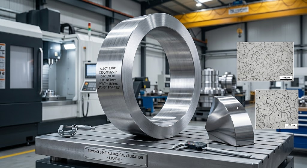
Grain Structure and Mechanical Properties
Cast 1.4841 components solidify with a coarse, dendritic grain structure that has random orientation and inherent porosity (microporosity and sometimes macroporosity from solidification shrinkage). Forging mechanically breaks down this cast structure through hot plastic deformation, producing a refined, equiaxed grain structure (typically ASTM grain size 5–8 in 1.4841 forgings made with our process controls). This refinement translates directly to higher and more isotropic impact toughness — critical for components subject to pressure pulses, water hammer, or thermal shock. In comparative testing on matched 1.4841 compositions, forgings consistently deliver 2 to 3 times the Charpy impact energy of sand castings in the longitudinal direction and significantly closer transverse-to-longitudinal toughness ratios.
Grain Flow and Fatigue Life
In a correctly designed forging, the plastic deformation flow lines follow the component geometry — around a ring's circumference, along a shaft's axis, or radially in a disk. This deliberate grain flow alignment means the highest principal stress in service aligns with the highest material strength direction. In a casting, there is no equivalent directionality. For rotating components (pump impellers, compressor discs) and for components subject to cyclic pressure loading (wellhead bodies, valve bonnets), the grain flow advantage of forging over casting translates to a factor of 2 to 5 improvement in high-cycle fatigue life.
Absence of Internal Defects
Castings in austenitic grades like 1.4841 are particularly prone to microporosity because the high alloying content depresses the solidification range and promotes gas entrapment. These micro-pores are not detectable by standard RT or UT in castings (due to grain scatter noise from the coarse cast structure) but become crack initiation sites in service under cyclic loading. Forgings, by definition, have had these solidification defects closed and welded shut by the compressive stresses of the forging operation, verified by the final UT inspection that can detect sub-millimeter planar defects reliably in the refined-grain forged structure.
✓ Real-World Impact
One of our German chemical industry customers switched from cast 1.4841 reactor nozzles to our forged equivalents after experiencing three nozzle cracking failures over a five-year period. The forged replacement nozzles have operated through two full reactor campaigns (totalling over 7 years) without a single inspection-revealed indication. The engineering root cause analysis attributed the original failures to casting microporosity at the nozzle-to-shell weld transition — a defect type that does not occur in forgings.
Quality Assurance System & Certifications
Our quality system is not a documentation exercise — it is an operational discipline that runs from the first raw material check to the final MTC review before dispatch. The following describes our actual process, not an aspirational policy statement.
Certifications and Standards Compliance
- ISO 9001:2015 — Quality Management System, scope covering forging, heat treatment, machining, and NDT of steel components
- API 6A (21st Edition) — We manufacture forging components to customer drawings and purchase specifications written to API 6A requirements. We do not hold the API Monogram license; customers who require API-Monogram-stamped assemblies should confirm their own licensing position. Our forgings supply the raw material and documentation that API-licensed assemblers require.
- EN 10228-3 and EN 10228-4 — Ultrasonic and magnetic particle testing of steel forgings, up to Level 4
- ASME SA-788 — Steel forgings general requirements; material procurement process meets ASME code provisions for pressure vessels and nuclear applications
- PED 2014/68/EU Compatible Documentation — Our EN 10204 Type 3.1 and 3.2 Mill Test Certificates provide the material traceability required by European Pressure Equipment Directive (PED 2014/68/EU) compliant assemblies. CE marking of pressure assemblies is the responsibility of the equipment manufacturer and their chosen Notified Body — we supply the certified forgings and accompanying documentation that feed into that process.
- Mill Test Certificate (MTC) 3.1 / 3.2 — Per EN 10204; 3.2 certificates countersigned by an independent third party inspection body (SGS, BV, TÜV, or Lloyds on request)
In-House Testing Capabilities
| Test Type | Equipment / Standard | Capability |
|---|---|---|
| Chemical Analysis | Optical Emission Spectrometer (OES) + C/S combustion analyser | All elements per EN 10095; N by fusion method |
| Tensile Testing | 500 kN servo-hydraulic universal testing machine | RT and elevated temperature (up to 1000°C in furnace) |
| Impact Testing | Charpy pendulum impact tester | RT and sub-zero testing (down to −196°C with liquid N₂ cooling) |
| Hardness Testing | Brinell (HBW), Vickers (HV), Rockwell (HRC) | 100% checking of all production forgings; HBW on all bar ends |
| Ultrasonic Testing | Phased Array UT (PAUT) + conventional A-scan UT | EN 10228-3 Levels 1–4; acceptance level per customer purchase order |
| Magnetic Particle Testing | Wet magnetic particle, fluorescent | EN 10228-1 Levels 1–4; acceptance level per customer purchase order |
| Dye Penetrant Testing | Solvent-removable penetrant system | EN 571 / ISO 3452; suitable for non-magnetic austenitic materials |
| Dimensional Inspection | CMM (Coordinate Measuring Machine), digital height gauge, precision bore gauge | Positioning accuracy ±0.01 mm |
| Metallography | Optical microscope + image analysis software | Grain size (ASTM E112), inclusion rating (ASTM E45), microstructure evaluation |
| Intergranular Corrosion Test | Strauss test (ASTM A262 Practice E) | Available upon request for sensitization-sensitive applications |
Quality Control Process Flow
- Incoming raw material inspection: OES analysis on every heat; comparison against mill certificate; heat number marking stamped before moving to production area
- Forging process monitoring: Temperature log printed from furnace controller for every charge; press load monitored by digital load cell; any deviation from pass schedule requires metallurgist approval before continuation
- Post-forging dimensional check: Hot dimensions measured before heat treatment; deviation from nominal requires assessment before proceeding
- Heat treatment verification: Temperature chart from certified recorder attached to each job card; hardness check on every forging immediately after heat treatment
- NDT inspection: UT, MT or PT performed by qualified NDT personnel holding relevant certification under national or international NDT personnel qualification schemes; results countersigned by QA manager
- Mechanical testing: Tensile and impact specimens cut from integrally forged prolongation or from a separately forged test coupon of the same heat, heated and heat treated identically to the production forging
- Final dimensional and visual: Full dimensional report against drawing; cosmetic surface condition per agreed acceptance criteria
- MTC preparation and review: All test results compiled, cross-checked against order requirements, reviewed by QA manager, then signed and released
- Packing and marking: Heat number and order number punch-stamped or low-stress vibro-etched; packing list and documents sealed inside moisture-proof packaging
Procurement Guide: How to Specify 1.4841 Forgings Correctly
Incorrect or incomplete specifications are the most common cause of delivery problems, unnecessary quality disputes, and — most seriously — components entering service that do not meet their design requirements. Our applications engineering team reviews hundreds of RFQs per year. The following guidance reflects the gaps we see most frequently.
Essential Information to Include in Your RFQ
- Material designation: Specify both the EN number (1.4841) and the designation (X15CrNiSi25-21). If you have additional chemistry restrictions (for example, tighter silicon control within the standard range, or a maximum nitrogen requirement), state them explicitly.
- Material standard: State EN 10095 for standard heat-resistant strip/bar property requirements, or your specific purchase specification if it adds requirements beyond the standard.
- Product form: Forged round bar / seamless ring / hollow forging / disk / plate — each has specific geometry requirements and reduction ratio implications.
- Dimensions and tolerances: Nominal dimensions plus tolerances for every critical dimension. For rings, specify OD, ID, and height with tolerances. For bars, specify diameter and length. "As forged" tolerance range should be agreed upfront — tight machined tolerances in rough-machined condition cost significantly more than standard forging tolerances.
- Delivery condition / heat treatment: Specify "+AT" (solution annealed) as the standard delivery condition for 1.4841. If you require a specific hardness range tighter than the standard, state it.
- NDT requirements: Specify the standard (EN 10228-3 for UT), the acceptance level (Level 3 or 4), and the coverage (100% volume scan vs. spot check). Absence of a stated NDT requirement does not mean NDT will be performed — we will seek clarification, but some suppliers will simply not test.
- Mechanical testing: Specify the test location (from integral prolongation or from representative test coupon), the number of tests required per heat, and which properties are mandatory vs. informational.
- Certificate type: EN 10204 type 3.1 (mill certificate) or 3.2 (third-party countersigned). If 3.2 is required, name the acceptable inspection bodies in your RFQ to avoid delays at order stage.
- Applicable design code: Stating ASME VIII, EN 13445, API 6A, or RCC-M (nuclear) alerts us to additional compliance requirements that may not be obvious from the material specification alone.
- Special requirements: ESR quality, Strauss corrosion test, positive material identification (PMI) on finished pieces, specific packing requirements for sea freight.
⚠ Common Specification Mistakes to Avoid
- Specifying only the ASTM grade equivalent (e.g. "310 stainless") without the EN material number — ASTM 310 and EN 1.4841 have overlapping but not identical chemistry ranges; confirm which specification governs
- Omitting heat treatment requirements — an as-forged (not annealed) 1.4841 component will have significantly higher hardness and lower toughness than the annealed condition, and may not meet design allowable stresses
- Requesting Charpy impact testing without specifying test temperature — for cryogenic or sub-ambient applications, room temperature Charpy values are insufficient
- Not specifying test coupon location for mechanical properties — a prolongation cut from the end of a round bar may have higher reduction ratio and therefore higher properties than the center section of a thick disk; your design calculations should be based on the lowest-property location
Failure Mode Analysis: When and Why 1.4841 Forgings Can Fail
Understanding failure mechanisms allows engineers to design them out before they occur in service. This section documents the primary failure modes observed in heat-resistant steel forgings and how proper material and process selection prevents them.
1. Sigma Phase Embrittlement
Sigma phase (σ) is a hard, brittle, topologically close-packed compound of approximate composition FeCr that forms in high-chromium austenitic alloys between 550°C and 850°C. It precipitates preferentially at grain boundaries and depletes the surrounding matrix of chromium, simultaneously reducing toughness and potentially creating paths for intergranular corrosion. In 1.4841, with its 24–26% chromium content, sigma phase formation kinetics are faster than in lower-chromium grades, meaning that components kept in service continuously at 700°C–800°C for tens of thousands of hours will develop sigma phase progressively.
Prevention: This is not necessarily a design-excluding condition — components that will never be removed from service and tested for toughness at ambient temperature may not be affected operationally. However, if the component needs to be removed for inspection or if emergency shutdown creates rapid cooling from operating temperature, the sigma-embrittled microstructure may crack under handling impact. The mitigation is to specify a solution anneal (re-heat to >1050°C, rapid cool) during any planned maintenance turnaround, which dissolves sigma phase and restores ambient toughness. We advise all customers with long-campaign service to factor this into their maintenance planning.
2. Hot Tearing During Forging (Supplier Process Failure)
Hot tearing is a forging defect caused by finishing the deformation at temperatures within the hot ductility trough — the temperature range where grain boundary liquation or segregation creates zones of reduced local ductility. In 1.4841, this trough occurs at approximately 900°C–1050°C in heats with higher silicon content. Forgings finished in this range develop internal or surface-breaking cracks that may be closed (invisible before machining) or open. The failure is a supplier process failure, not a material failure — our process controls specifically prevent finishing in this range. When evaluating alternative suppliers, ask whether they have documented forging temperature monitoring for 1.4841 specifically.
3. Intergranular Corrosion (Sensitization)
While 1.4841's carbon content (up to 0.20%) is higher than 310S's 0.08%, sensitization — chromium carbide precipitation at grain boundaries causing chromium depletion and intergranular corrosion susceptibility — can occur if the component is heated in the sensitization range (450°C–900°C) during welding or improper post-weld heat treatment. For applications where sensitization is a concern (aqueous corrosion environments), a post-fabrication solution anneal should be specified. If post-fabrication heat treatment is not possible, discuss whether a lower-carbon heat of 1.4841 (achievable within the standard range) or switching to 1.4845 (310S, 0.08% max C) is a better design choice.
4. Thermal Fatigue Cracking
Components subject to large numbers of thermal cycles — furnace door hardware, quench tank fixtures, burner nozzles — can develop thermal fatigue cracks that initiate from the surface and propagate inward. Thermal fatigue life is governed by the thermal strain range per cycle (ΔT × coefficient of thermal expansion), the elastic modulus (which determines stress magnitude for a given strain), and the high-temperature low-cycle fatigue properties of the alloy. 1.4841's relatively high thermal expansion coefficient (17.5 × 10⁻⁶/K) means that large temperature swings create significant thermal strain, but its forged microstructure provides substantially better fatigue crack initiation resistance than cast equivalents. For applications with >10,000 thermal cycles anticipated over service life, contact our engineering team for a design life assessment.
Documented Application Cases for 1.4841 Forgings from Jiangsu Liangyi
The following cases describe actual projects our team has executed, including the engineering challenges, our manufacturing approach, and the verified service outcomes. We share this detail because it demonstrates both our technical capability and our commitment to accountability for component performance.
Case 1 — Saudi Arabia HTHP Wellhead Equipment
Application context: A major oilfield operator in Saudi Arabia was developing a high-temperature, high-pressure gas condensate field where bottomhole temperatures exceeded 180°C and wellhead operating pressures reached 690 bar (10,000 psi). Standard carbon steel wellhead equipment was excluded by the combined corrosion risk from CO₂-saturated brine and the temperature range, which exceeded the normal API 6A carbon steel allowable temperature.
Engineering challenge: The customer required 1.4841 forgings, NACE MR0175 compliant (HRC ≤22 in solution-annealed condition) for all surface-wetted components, 100% UT per API 6A Appendix F and full MTC 3.2 certification. The largest components were casing head bodies weighing up to 850 kg finished weight, which had to be forged from ingots weighing over 2000 kg.
Our solution: We manufactured 580 individual parts across 14 product lines such as Christmas tree bodies, casing heads, tubing heads, valve bonnets and spacer spools. All pressure retaining parts were of ESR quality steel. Each forging was solution annealed and verified for hardness (confirmed HRB 92–96, equivalent to HRC ≤22) before dispatch. Full documentation package including MTC 3.2 (countersigned by SGS), UT reports, and dimensional inspection records was compiled for each item.
Service outcome: All 580 components were installed successfully over a 14-month campaign. As of the last operator feedback (received 6+ years post-installation), no inspection or field replacement has been required for any forging in this supply package.
Case 2 — German Specialty Chemical Reactor Nozzles
Application context: A specialty chemical producer in Germany was constructing a new high-temperature catalytic reactor for a pharmaceutical intermediate process. The reactor shell was 2.4851 (Alloy 601) but budget constraints required the nozzle forgings — which see the highest combined corrosion and thermal stress — to be in a less expensive alloy while meeting the same design life criteria.
Engineering challenge: The nozzle forgings operate at 920°C in an atmosphere containing trace sulfur compounds and are subject to startup/shutdown thermal cycling approximately 4 times per year. The customer had previously used cast 310S nozzles that failed (intergranular corrosion after carburization) after 3–4 years. The new design required a 10-year minimum service life.
Our solution: We recommended and supplied forged 1.4841 nozzle blanks in solution-annealed condition, demonstrating via published literature data that 1.4841's higher silicon content provides meaningfully better carburization resistance than 310S in sulfur-containing atmospheres. We supplied 120 nozzle forgings with EN 10204 Type 3.2 MTCs and a technical justification document comparing 1.4841 vs. 310S oxidation and carburization performance for the customer's engineering files.
Service outcome: Post-installation feedback received after the second scheduled inspection (approximately 5.5 years service) confirmed zero rejection of any nozzle during visual or PT inspection. Wall thickness measurements at the external oxide zone showed a corrosion rate consistent with projected 12-year service life — exceeding the 10-year design requirement. The customer has since standardized on forged 1.4841 for all nozzle applications in their high-temperature reactors.
Case 3 — Indian Thermal Power Plant Turbine Components
Application context: An EPC contractor for 3x660 MW ultra-supercritical thermal power plants in India specified 1.4841 forged components for steam turbine extraction chambers, high pressure valve bodies and pump casing halves for the boiler feed pump system.
Engineering challenge: The turbine components required ASME SA-182 equivalent properties, ASTM A262 Practice E (Strauss corrosion test) for sensitization verification, and dimensional tolerances equivalent to ISO 286 grade IT9 on all machined surfaces. Total component weight per plant was approximately 12 tonnes; the project required all three plants' components within a 9-month delivery window.
Our solution: We structured a dedicated production cell for this project, manufacturing 127 forging items across the three plant sets. Component complexity ranged from simple disk blanks (< 100 kg) to multi-step turbine valve bodies exceeding 3,500 kg. All components were Strauss-tested, with results within specification (no evidence of intergranular attack). Delivery was completed 3 weeks ahead of the 9-month target, allowing the EPC contractor to accelerate their mechanical completion schedule.
Service outcome: All three power plants are in commercial operation. The EPC contractor has included Jiangsu Liangyi on their approved vendor list for all subsequent thermal power projects requiring heat-resistant steel forgings.
Case 4 — Chinese Nuclear Power Plant Reactor Coolant Pump Components
Application context: A domestic nuclear power plant operator required forgings for non-pressure-retaining internal components of the reactor coolant pump (RCP), such as the seal chamber housing and the bearing retention ring. These components are in continuous contact with primary coolant at 280°C - 320°C and must have absolute dimensional stability over a 60 year plant design life.
Engineering challenge: Material documentation for the purchase order included heat number level traceability, positive material identification (PMI) on finished components, and third party witness inspection at multiple hold points. The customer’s quality plan stipulated that manufacturing procedure specifications (MPS) and weld procedure qualification records (WPQ) had to be submitted prior to production.
Our solution: We produced ESR-refined 1.4841 forgings from a pre-qualified ingot heat. The production schedule included customer-specified hold points for third-party witness inspection at incoming material verification, post-forging UT, and final dimensional inspection. All documentation was compiled into a comprehensive quality dossier per the customer's purchase specification requirements.
Service outcome: All components passed incoming and in-process inspections and were accepted by the customer. The customer subsequently placed follow-on orders for the same component families on subsequent units.
The Jiangyin Forging Cluster: Why Our Location Delivers for You
Jiangyin is not an arbitrary factory location — it is one of China's most concentrated heavy manufacturing clusters, and that concentration directly affects the quality and delivery reliability of components you purchase from us.
Raw Material Proximity and Supply Chain Reliability
Within 60 km of our factory, there are several of China's largest specialty steel producers, including mills with dedicated ESR and VAR (Vacuum Arc Remelting) capacity for superalloy-grade inputs. This proximity means our raw material lead time for standard 1.4841 grades is typically 2–3 weeks from order placement — a fraction of what forging companies in regions without nearby specialty steel production face. When a heat fails incoming inspection (rare, but it happens in all forge shops), we can obtain a replacement heat within days rather than weeks, protecting your delivery schedule.
Logistics: 120 km from Shanghai Port
Shanghai Port handles approximately 50 million TEU annually — more than any other port in the world. Our factory's proximity means standard shipping from our dock gate to the port terminal is a single-day road haul. We have established forwarding relationships with three major freight brokers based in Shanghai who provide priority booking for project cargo (out-of-gauge or heavy lift items that cannot be containerized). For urgent orders, express air freight from Shanghai Pudong Airport is also a viable option for smaller forgings up to approximately 200 kg.
Specialized Technical Workforce
Jiangyin's forging industry has been operating continuously for over 40 years. This has created a local technical workforce — forge operators, heat treaters, NDT inspectors, and metallurgists — with forging-specific experience that is genuinely difficult to replicate in regions where heavy industry is newer. Many of our senior forge operators have been working on austenitic heat-resistant grades for 15–20 years. This depth of practical knowledge is the reason our 1.4841 process yields are high and our rework rate is low.
Frequently Asked Questions About 1.4841 Forgings
Contact Jiangsu Liangyi for 1.4841 Forging Quotations
Jiangsu Liangyi Co., Limited provides complete technical and commercial support for 1.4841 (X15CrNiSi25-21) forging projects of all sizes. When you contact us, you will be connected with a technically trained sales engineer — not a general sales representative — who can review your drawings, discuss your service conditions, and propose the correct material specification, delivery condition, and quality documentation package.
Please send us your inquiry with as much technical context as possible: component drawings (PDF or DXF), material specification, service conditions, applicable design code, required certifications, and target quantity and delivery date. We commit to providing a full technical and commercial response within 24 business hours.
Inquiry Email: sales@jnmtforgedparts.com
Phone / WhatsApp: +86-13585067993
Website: https://www.jnmtforgedparts.com
Address: Chengchang Industry Park, Jiangyin City, Jiangsu Province, China
Business Hours: Monday–Friday, 08:00–18:00 (UTC+8)