1.4988 X8CrNiMoVNb16-13 Forging Parts | Complete Metallurgical Guide & Custom Manufacturer
1.4988 X8CrNiMoVNb16-13 — Authoritative Quick Reference
1.4988 X8CrNiMoVNb16-13: Material Identity, Engineering Background & Why It Was Developed
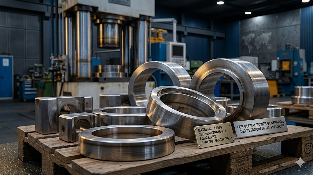
Established in 1997, Jiangsu Liangyi Co., Limited is an ISO 9001:2015 certified manufacturer of 1.4988 X8CrNiMoVNb16-13 forging parts with 25+ years of focused expertise in high-temperature alloy forging, an 80,000 ㎡ production facility and 120,000-ton annual capacity. We supply clients across 50+ countries in Europe, North America, the Middle East, Southeast Asia, Australia and South America.
1.4988 (EN designation X8CrNiMoVNb16-13) belongs to the metallurgical family of precipitation hardenable austenitic heat-resistant steels — a class engineered in the 1960s–1980s as European power plant operators pushed steam turbine parameters beyond 540°C into the supercritical and ultra-supercritical (USC) regimes. Conventional austenitic grades such as 316H became inadequate: their strength decayed rapidly above 550°C because solid-solution strengthening loses effectiveness as thermal vibration assists dislocation movement. The engineering response was to design steels that carry their strengthening mechanism in the form of thermally stable precipitate particles that resist dislocation movement even at elevated temperature.
The resulting grade — governed by EN 10222-5 for pressure-purpose forgings and DIN 17459 for seamless tubes — became the workhorse for European USC turbine spindles, valve stems and high-temperature fasteners. Components designed to its allowable stresses routinely achieve 200,000+ operating hours (approximately 23 years of continuous service) without material-related failure, as documented by European power plant maintenance records. This is the real-world performance baseline that differentiates 1.4988 from cheaper substitute grades.
Alloy Design Philosophy: What Every Element in X8CrNiMoVNb16-13 Actually Does
The composition of 1.4988 is not arbitrary. Every element range reflects a specific metallurgical function, and the interactions between elements produce a performance profile that cannot be replicated by simply substituting one element for another. Understanding this makes it possible to evaluate proposed substitutes critically and to avoid the costly procurement errors described later in this guide.
The Austenite Stability Foundation (Cr + Ni)
The 15.5–17.5% Chromium and 12.5–14.5% Nickel combination keeps the Schaeffler-Delong constitution diagram firmly in the fully austenitic zone, with a calculated Creq/Nieq ratio well below the threshold for delta-ferrite formation during solidification. This is not merely about phase constitution: delta ferrite, if present, accelerates sigma phase precipitation by orders of magnitude during high-temperature service, because sigma phase nucleates preferentially at ferrite/austenite interfaces rather than austenite grain boundaries. The absence of ferrite in correctly processed 1.4988 is therefore a prerequisite for the long-term phase stability that makes 200,000-hour design lives achievable.
The Dual Precipitate Strengthening System (Nb + V + N)
The engineering innovation that distinguishes 1.4988 from solid-solution austenitic grades is its deliberate dual-precipitate design. Two populations of nanoscale particles form during aging, operating on complementary length scales and at different temperatures:
- Niobium carbonitrides (NbCN, primary precipitate): Form first during cooling from solution annealing temperature (approximately 1050–1100°C), appearing at both grain boundaries and matrix. Grain-boundary NbCN particles are larger (50–200 nm) and act as powerful grain boundary pinning agents — they are the mechanism that prevents austenite grain coarsening during forging and subsequent heat treatment, ensuring fine-grained, uniformly tested microstructures in thick-section forgings. Intragranular NbC particles (20–80 nm) also block dislocation climb during high-temperature creep, contributing to long-term creep resistance in the 500–600°C range.
- Vanadium nitrides (VN, secondary precipitate): Precipitate during the aging step (750–880°C), forming an extremely dense population of very fine particles (5–30 nm) distributed uniformly throughout the grain interior. This high particle density creates a strong barrier to dislocation glide — the primary mechanism of plastic deformation at moderate temperatures. VN particles are responsible for the majority of the yield strength increase from the +AT to the +P condition (typically +80 to +120 MPa) and for the superior fatigue resistance of 1.4988 compared to solution-annealed austenitic grades.
- The Nitrogen amplifier effect: Nitrogen (0.060–0.140%) dramatically increases the volume fraction and number density of VN precipitates during aging. Higher N within the specification range produces smaller, more numerous VN particles — a finer particle distribution that gives higher yield strength and better fatigue performance. Nitrogen also stabilises the austenite matrix, reducing the risk of deformation-induced martensite transformation during cold straightening operations and contributing approximately 40–60 MPa additional solid-solution strengthening to the aged yield strength.
Molybdenum: Three Simultaneous Functions
The 1.10–1.50% Molybdenum in 1.4988 provides three simultaneous benefits that justify its cost premium: (1) Solid-solution strengthening — Mo atoms create local lattice distortions that impede dislocation movement, providing approximately 15–25 MPa additional yield strength; (2) Creep resistance enhancement — Mo segregates to grain boundaries during high-temperature service, slowing grain boundary diffusion and reducing grain boundary sliding, which is the dominant creep mechanism at 550–650°C in austenitic steels; (3) Pitting corrosion resistance — Mo raises the Pitting Resistance Equivalent Number (PREN = %Cr + 3.3×%Mo + 16×%N) to approximately 21–24, providing meaningful resistance to chloride-initiated pitting in cooling water, seawater and process environments — a practical benefit for power plant components in coastal locations and offshore petrochemical installations.
Carbon: The Narrow Range with Critical Consequences
The 0.04–0.10% Carbon range is deliberately maintained above the ultra-low carbon level of grades like 316L, because carbon contributes to strengthening through M₂₃C₆ carbide precipitation at grain boundaries during aging and service. However, carbon above 0.10% creates a sensitization risk: in the temperature range 425–850°C, M₂₃C₆ precipitation depletes chromium at grain boundaries to below the ~12% threshold for passive film stability, leaving the grain boundary zone vulnerable to intergranular corrosion and intergranular stress corrosion cracking. Niobium resolves this dilemma by preferentially bonding carbon as stable NbC (which forms at ~1050–1200°C, well above the sensitization zone), effectively "fixing" the carbon before it can participate in M₂₃C₆ formation. This is the fundamental reason 1.4988 tolerates a higher carbon content than sensitization-prone grades while maintaining superior corrosion resistance.
Silicon: The Sub-Scale Barrier Mechanism
Silicon (0.30–0.60%) is mechanistically underappreciated in most material data sheets. In high-temperature oxidising service, Si selectively oxidises to SiO₂ beneath the primary Cr₂O₃ protective scale. This silica sub-layer is a nearly impermeable barrier to oxygen ion (O²⁻) inward diffusion — the rate-limiting step in oxide scale growth. The practical effect is that 1.4988 components with controlled Si at 0.50–0.60% exhibit significantly thinner, more protective oxide scales after 10,000+ hours at 700°C compared to components at the lower specification limit, as confirmed by cross-section analysis of field-returned European power plant components at overhaul intervals. This sub-scale mechanism is the principal reason 1.4988 achieves scaling resistance to 750°C despite having lower Cr than grades like 310S (25% Cr) — the Si amplifies the effectiveness of the available Cr.
Phase Stability & Sigma Phase Risk in Long-Term 1.4988 Service: What Plant Engineers Must Know
One of the most consequential — and least discussed — long-term material behaviour topics for 1.4988 components in extended service is the question of phase stability: do the beneficial precipitate phases (NbCN, VN) remain stable throughout the design life, and does the deleterious sigma phase (σ) form to a level that compromises mechanical integrity?
What is Sigma Phase and Why Does It Matter?
Sigma phase is an ordered intermetallic compound, primarily (Fe,Cr)ₓ(Ni,Mo)y, that forms in iron-chromium-nickel alloys when exposed to temperatures between approximately 600°C and 900°C for extended periods. It is extremely brittle — with near-zero room-temperature fracture toughness — and forms preferentially at grain boundaries and at the boundaries between matrix and existing precipitate particles. In components that experience thermal cycling, sigma phase particles at grain boundaries become preferred crack initiation sites, leading to intergranular brittle fracture at stresses far below the design yield strength. This type of failure is insidious because hardness surveys during routine maintenance do not detect sigma phase formation — impact toughness testing is required.
Sigma Phase Risk in 1.4988 vs Other Grades
The sigma phase formation kinetics in 1.4988 are substantially slower than in duplex, ferritic or lower-nickel austenitic grades, for three compositional reasons:
- High Nickel content (12.5–14.5%): Ni is a potent sigma phase suppressor because it does not participate in the sigma phase structure. Higher Ni expands the austenite phase field and raises the activation energy for sigma phase nucleation, shifting the nose of the sigma phase formation C-curve on the TTT diagram to longer times.
- Absence of delta ferrite: As noted above, sigma phase nucleates orders of magnitude faster in ferritic/duplex grades because ferrite acts as a fast-diffusion pathway for Cr and Mo redistribution. The fully austenitic matrix of 1.4988 eliminates this nucleation advantage.
- Molybdenum content (1.10–1.50%): Mo partitions into sigma phase and accelerates its formation relative to Mo-free grades, which partially offsets the Ni and ferrite-free advantages. However, at 1.1–1.5% Mo (compared to 2.5–3.5% Mo in superduplex steels), the effect is minor.
Field-metallurgical examination of 1.4988 turbine spindle sections from European power plants at 100,000-hour intervals has consistently shown only trace sigma phase formation (below 1 vol%), with Charpy impact toughness values at room temperature remaining above 40 J even after such service periods. This confirms that sigma phase is not a limiting factor for correctly specified and heat-treated 1.4988 components within normal 200,000-hour design life frameworks.
Precipitate Coarsening: The More Relevant Long-Term Concern
A more practically significant long-term microstructural change in 1.4988 during service at 600–650°C is precipitate coarsening (Ostwald ripening): the fine VN precipitates that provide room-temperature yield strength gradually increase in average size and decrease in number density over service time, as thermodynamic equilibrium drives matter from smaller to larger particles. This reduces yield strength and fatigue resistance over time — the magnitude depends on service temperature and time. After 100,000 hours at 650°C, yield strength reduction of 15–25 MPa relative to the fresh-aged condition is typical, which is accommodated by the design safety factors in pressure vessel codes but should be considered in life extension assessment studies.
Plant maintenance recommendation: For 1.4988 turbine components approaching or exceeding 100,000 operating hours, we recommend a combined impact toughness test and yield strength test on representative material from the next scheduled overhaul sampling programme. This quantifies the extent of both sigma phase embrittlement (if any) and precipitate coarsening, providing the data needed for accurate remaining life assessment.
Precipitation Kinetics of 1.4988: Understanding the TTT Diagram & Optimal Aging Window
The Time-Temperature-Transformation (TTT) diagram for 1.4988 shows how the microstructure of the alloy changes over time and temperature during isothermal heat treatment. Heat treatment engineers can improve the aging cycle for specific application needs by knowing its most important features. This could mean getting the best room-temperature yield strength, long-term creep resistance, or a good mix of both.
Key Features of the 1.4988 TTT Diagram
The TTT diagram for 1.4988 (schematically, not reproduced from any external source) exhibits three distinct C-curve systems, each representing a different transformation product with a different effect on final properties:
- NbCN C-curve (800–1100°C nose): NbCN particles precipitate relatively rapidly in the range 900–1100°C (hours timescale at 950°C, minutes at 1050°C). During controlled forging and cooling after hot work, some NbCN always forms — this is acceptable and beneficial, as it pins grain boundaries during solution annealing. However, heavy NbCN precipitation during slow cooling from forging temperature without subsequent solution annealing produces a coarse, inhomogeneous particle distribution that impairs toughness and provides less effective grain boundary pinning than fine, re-precipitated NbCN.
- VN C-curve (650–900°C nose): VN precipitation has its nose approximately at 780–820°C. At this temperature, the precipitation half-time is approximately 30–90 minutes for typical 1.4988 compositions. Below 700°C, precipitation is sluggish (>10 hours for significant VN formation); above 880°C, VN particles begin to dissolve back into solid solution. This C-curve geometry defines the practical aging temperature window of 750–880°C: aging below 750°C requires excessively long times to achieve full precipitation; aging above 880°C risks partial dissolution and residual austenite with reduced N content, giving weaker, coarser precipitates on cooling.
- M₂₃C₆ C-curve (500–850°C nose): M₂₃C₆ carbide precipitation in 1.4988 is substantially retarded by the NbC-fixed carbon (Nb preferentially bonds C, leaving less free carbon for M₂₃C₆ formation). The C-curve nose is approximately at 700–750°C with a half-time of several hours — significantly slower than in unbuffered austenitic grades. This retardation is why 1.4988 can be welded with interpass temperatures up to 150°C without immediate sensitization risk, provided the total heat input is controlled.
Aging Temperature vs. Final Properties: The Engineering Trade-Off
| Aging Temp. (°C) | VN Particle Size | RT Yield Strength Effect | Creep Resistance (600°C) | Best For |
|---|---|---|---|---|
| 750 – 780 | Finest (5–15 nm) | Highest Rp0.2 (+120 MPa vs AT) | Moderate (particles overage faster in service) | High-cycle fatigue components; fasteners |
| 800 – 830 | Medium (10–25 nm) | Balanced (+90 to +100 MPa) | Good balanced performance | General turbine spindles, valve stems |
| 850 – 880 | Coarser (20–40 nm) | Lower (+60 to +80 MPa) | Best (particles most stable at service temp.) | USC rotor forgings; long-life creep service |
Engineering insight: For European USC power plant turbine spindle applications designed to ECCC (European Creep Collaborative Committee) allowable stresses at 600–650°C, aging in the upper range (830–870°C) is preferred by most OEM specifications, despite delivering lower room-temperature yield strength. The rationale is that coarser precipitates are more stable against service-temperature coarsening, maintaining their strengthening effect more consistently over the 200,000-hour design life. Fatigue-critical rotating components such as disc forgings are sometimes specified at the lower aging temperature range to maximise yield strength for disc-burst safety margin calculations.
Chemical Composition of 1.4988 X8CrNiMoVNb16-13 per EN 10222-5
The composition below represents the melt (ladle) analysis limits as specified in EN 10222-5. All values are mass %. Full heat-by-heat traceability between ladle analysis certificate and finished forging serial number is maintained throughout our production records and MTC documentation.
| Element | Symbol | Mass % (Melt) | Role & Consequence of Out-of-Range |
|---|---|---|---|
| Carbon | C | 0.04 – 0.10 | Strength via carbide precipitation; <0.04% → insufficient NbC; >0.10% → sensitization risk if Nb insufficient |
| Silicon | Si | 0.30 – 0.60 | SiO₂ sub-scale barrier; <0.30% → reduced scaling resistance at 700°C+ |
| Manganese | Mn | max. 1.50 | Austenite stabiliser, hot ductility; >1.5% no benefit, elevated MnS inclusions impair UT |
| Phosphorus | P | max. 0.035 | Tramp element; segregates to grain boundaries → embrittlement; strictly minimised in premium heats |
| Sulphur | S | max. 0.015 | Forms MnS inclusions; >0.015% creates UT scattering and anisotropic toughness in thick forgings |
| Nickel | Ni | 12.50 – 14.50 | Austenite stabiliser, sigma phase suppressor; <12.5% → risk of delta ferrite; >14.5% → unnecessary cost |
| Chromium | Cr | 15.50 – 17.50 | Cr₂O₃ scale former; <15.5% → inadequate scaling resistance; >17.5% → sigma phase formation accelerated |
| Molybdenum | Mo | 1.10 – 1.50 | Solid-solution + creep strengthening, PREN; <1.1% → inadequate creep contribution; >1.5% → sigma risk increase |
| Vanadium | V | 0.60 – 0.85 | VN precipitate source; <0.60% → insufficient yield/fatigue strength response; >0.85% → coarse primary VC |
| Nitrogen | N | 0.060 – 0.140 | VN amplifier + austenite stabiliser; <0.06% → weak aging response; >0.14% → porosity risk at solidification |
| Niobium | Nb | 10×C% to 1.20 | Carbon fixer (NbC prevents sensitization) + grain boundary pinner; below 10×C% → free C available for M₂₃C₆ sensitization |
Critical sourcing note — melt vs. product analysis: EN 10222-5 composition limits are defined for ladle (melt) analysis. Product analysis from finished forgings is subject to wider tolerance allowances per EN 10021. Always verify your MTC reports the original ladle analysis by heat number — not product analysis only. Suppliers who provide only product analysis certificates cannot guarantee conformance to the narrower melt limits that are the basis of all published material property data for this grade.
1.4988 vs. Competing High-Temperature Grades: Engineering Decision Guide
Selecting the optimal grade requires evaluating multiple performance dimensions simultaneously. The following comparison covers the grades most commonly considered alongside 1.4988, using objective published data and field performance observations from our 25+ years of supply experience.
| Criterion | 1.4988 X8CrNiMoVNb16-13 | 1.4919 316H | 1.4878 321H | 1.4845 310S | A286 (S66286) | Incoloy 800H |
|---|---|---|---|---|---|---|
| Strengthening Mechanism | Dual Nb+V precipitates | Solid solution only | TiC stabilised | Solid solution only | γ' + NbC precipitates | Carbides + γ' |
| Design Temp. Limit (10⁵h) | 650 °C | 550 °C | 580 °C | High-Cr, low-stress only | 650 °C | 750 °C |
| Scaling Resistance (cont.) | 750 °C | 925 °C | 900 °C | 1100 °C | 650 °C | 1100 °C |
| Creep Rupture 600°C / 10⁵h (MPa) | ~80 | ~40 | ~50 | ~30 | ~90 | ~55 |
| RT Yield Strength (MPa, min.) | 255 (+P) | 205 | 205 | 205 | 620 (+A) | 170 |
| Pitting Resistance (PREN) | 21 – 24 | 24 – 26 | 18 – 20 | 26 – 29 | 14 – 16 | ~20 |
| Sigma Phase Susceptibility | Low | Low | Low | Moderate (high Cr) | Low | Very Low |
| SRC Susceptibility | Moderate (precipitate hardened) | Low | Low | Low | High | Low-Moderate |
| Weldability | Good (with PWHT) | Excellent | Excellent | Fair (hot cracking risk) | Difficult | Good |
| Forgeability (large section) | Good (>500 mm dia.) | Excellent | Excellent | Good | Fair (<500 mm preferred) | Fair (hot working window) |
| Governing Standard | EN 10222-5 | EN 10222-5, A182 | EN 10222-5, A182 | EN 10222-5, A182 | AMS 5731, A638 | EN 10222-5, B407 |
| Typical Application | USC turbine spindles, rings | Sub-critical boiler fittings | Super-critical pipe hangers | Furnace components | Aerospace disc bolts | Reformer tubes, 750°C+ |
| Relative Material Cost | Medium-High | Medium | Medium | Medium | High | Very High |
Do not substitute 316H or 321H for 1.4988 in creep-loaded turbine service. At 600°C / 10⁵h, 316H provides only ~40 MPa creep rupture strength versus ~80 MPa for 1.4988. A component designed to 1.4988 allowable stresses and manufactured from 316H is structurally under-designed by approximately 2:1 in creep loading — constituting a potentially catastrophic safety deficiency that cannot be detected by standard room-temperature mechanical testing or hardness survey.
1.4988 Forging Process: Temperature Windows, Reduction Ratios, Grain Flow & Quality Control
Melting Route and Ingot Quality
- Electric Arc Furnace (EAF) — bulk scrap melting; initial alloy addition of Cr, Ni, Mo, Mn
- Argon Oxygen Decarburisation (AOD) — carbon reduction to 0.04–0.10%; precise N injection to 0.060–0.140%; V and Nb addition in this stage for best compositional homogeneity
- Ladle Furnace (LF) refining — final composition trim; slag refining to reduce inclusions; desulphurisation to max 0.010–0.015%S; temperature homogenisation prior to casting
- Vacuum Degassing (VD) — H₂ removal to <2 ppm (prevents hydrogen-induced flakes in thick forgings); O₂ reduction improves UT noise-to-signal ratio; standard for all forgings >5 tonnes
- Electro-Slag Remelting (ESR) — premium option: reduces macro-segregation by 60–80%, removes oxide inclusions, improves UT testability to Class 4; mandatory for rotating turbine disc forgings and specified high-integrity applications
Hot Forging Temperature Window
| Stage | Temperature (°C) | Metallurgical Rationale |
|---|---|---|
| Soak before first blow | 1150 – 1200 °C | Full dissolution of NbCN residuals from casting; homogenisation of Nb/V segregation from ingot solidification |
| Start of open die forging | 1100 – 1150 °C | Sufficient ductility for ingot breakdown; no risk of surface cracking at this temperature for 1.4988 |
| Intermediate passes | 1050 – 1100 °C | Grain refinement occurs by dynamic recrystallisation; controlled pass reduction per stroke (max 20% per pass to avoid adiabatic shear) |
| Final forging pass | 1000 – 1050 °C | Defines final shape and grain size; controlled deformation ensures static recrystallisation during subsequent dwell at forging temperature |
| Critical stop temperature | <950 °C — STOP FORGING | Below 950°C: NbC particles reprecipitate during deformation → bimodal grain structure → property non-uniformity → UT rejection risk |
Grain Flow Optimisation for Fatigue Life — A Factor Competitors Rarely Discuss
The direction of principal grain flow (forging fibre direction) relative to the operating stress axis has a profound effect on the fatigue life of 1.4988 rotating components. This is well-established in fracture mechanics but rarely addressed in commercial forging supplier documentation:
- Longitudinal grain flow parallel to stress axis: The best configuration for rotating shafts and spindles. Fatigue crack propagation must cross grain boundaries oriented perpendicular to the crack plane, which requires significantly higher crack tip stress intensity (by a factor of 1.5–2×) compared to transverse orientation. Our forging layout specifies longitudinal axis parallel to the bar axis for shaft-type forgings.
- Tangential grain flow in ring forgings: For seamless rolled rings, rolling produces grain flow in the tangential (circumferential) direction — aligned with the principal hoop stress in pressurised rings. This orientation provides maximum resistance to radial fatigue cracking, which is the dominant failure mode for high-pressure containment rings.
- Radial grain flow (avoid): Machined-from-solid disc or ring forgings cut from a round bar have radial grain flow in the web region, where fatigue cracks propagate fastest. This is why ring-rolled blanks for turbine rings are preferred over machined-from-solid for fatigue-critical applications — and why the cost premium for seamless ring rolling over bar stock is justified by the fatigue life improvement, which can exceed 3× in rotating disc applications.
Minimum Forging Reduction Ratio Requirements
| Product Type | Min. Reduction Ratio | UT Class Achievable | Application Driver |
|---|---|---|---|
| Standard forged bars / shafts | 3:1 | EN 10228-3 Class 3 | EN 10222-5 minimum; non-rotating pressure vessel fittings |
| Turbine rotors and discs | 4:1 (ESR ingot preferred) | EN 10228-3 Class 4 | Rotating safety-critical; disc-burst safety margin requires full grain refinement |
| High-pressure fasteners / studs | 5:1 | ASTM A388 Class 3 + surface PT | Fatigue life dominates; maximum fibre alignment required |
| Seamless rolled rings | 5:1 total ring roll ratio | EN 10228-3 Class 3–4 | Ring rolling provides continuous radial-tangential forging equivalent |
| Thick pressure vessel shells | 3:1 minimum; 4:1 preferred | EN 10228-3 Class 3 | Mandrel pressing consolidates centre; higher ratio eliminates ingot-centre porosity |
Heat Treatment of 1.4988: Two-Stage Process, Parameters & Critical Control Points
The two-stage heat treatment sequence — solution annealing followed by precipitation hardening — transforms the forged blank from a heavily worked, inhomogeneous microstructure into a fine-grained, uniformly precipitate-strengthened component ready for final machining and NDT. Both stages require equally rigorous control; failure in either stage cannot be fully compensated by the other.
Stage 1: Solution Annealing (Homogenisation + Grain Refinement)
| Parameter | Specification | Consequence of Deviation |
|---|---|---|
| Temperature | 1100 – 1150 °C | <1100°C: Residual coarse NbCN undissolved → inhomogeneous grain boundary pinning → grain size scatter in final product; >1150°C: Abnormal grain growth risk, especially in fine-grained billet regions adjacent to forgings |
| Soaking time | min. 1.0 h (≤100 mm section); +30 min per additional 50 mm thickness; max. 4.0 h (to avoid excessive grain coarsening) | Insufficient time → centre of thick sections remains under-annealed; excess time → grain coarsening reduces toughness and fatigue life |
| Furnace atmosphere | Neutral or slightly reducing (N₂/H₂ mixture for bright annealing); controlled slightly oxidising for air furnaces | Strongly reducing: surface decarburisation reduces surface hardness and fatigue strength; strongly oxidising: scale forms that must be removed by subsequent pickling or grit blasting |
| Cooling rate through sensitisation zone (850–425°C) | min. 5 °C/s (water quench or controlled air for sections ≤50 mm) | <5°C/s → grain boundary M₂₃C₆ precipitation → Cr depletion → sensitization → risk of intergranular corrosion attack and intergranular SCC in service |
| Target ASTM grain size | ASTM 3–6 (client drawing specifies if tighter) | Coarser (ASTM 1–2): better creep resistance but reduced fatigue life; finer (ASTM 7+): better fatigue but reduced creep rupture life; confirm with client for each application |
Stage 2: Precipitation Hardening (Aging)
| Parameter | Specification | Consequence of Deviation |
|---|---|---|
| Temperature | 750 – 880 °C (see aging temperature engineering trade-off section) | <750°C: Insufficient VN precipitation → below minimum Rp0.2; >880°C: partial VN re-solution → weaker, coarser reprecipitation on cooling → Rp0.2 lower than maximum achievable; sigma phase risk if >900°C |
| Soaking time | 1.0 h (thin sections ≤50 mm); 2–4 h (100–300 mm sections); 6–8 h (sections >300 mm) | Under-aging: centre of thick section remains under-precipitated; over-aging: precipitate coarsening reduces room-temperature yield strength |
| Temperature uniformity | ±10 °C across furnace load (automatic recording; calibrated per instrument calibration schedule) | >±15°C variation: property non-uniformity across a single forging; components from cool zones may not meet Rp0.2 minimum |
| Cooling method | Air cool to ambient; quenching not required or beneficial | Quenching from aging temperature adds residual stress without improving properties; slow furnace cooling below 700°C acceptable and slightly improves creep resistance |
| Hardness after aging | 200 – 260 HBW (production QC) | <200 HBW suggests under-aging or incorrect heat; >260 HBW suggests over-aged precipitation or incorrect material identity |
Repair and modification after aging: Any forging that undergoes welding, significant straightening or dimensional correction after precipitation hardening must be re-solution annealed and re-aged from scratch. Partial re-aging without prior re-annealing produces a bimodal precipitate distribution — over-aged particles from the first treatment coexisting with fresh fine particles from the re-age — that gives inconsistent hardness values and cannot be reliably characterised by room-temperature mechanical tests. This is one of the most commonly overlooked requirements in repair and modification procedures.
Mechanical Properties of 1.4988 X8CrNiMoVNb16-13: Room Temperature, Elevated Temperature, Creep & Thermal Fatigue
Room Temperature Properties — EN 10222-5 Requirements vs Jiangsu Liangyi Typical Values
| Property | Unit | Orientation | EN Minimum / Range | Our Typical Achieved |
|---|---|---|---|---|
| Tensile Strength (Rm) | MPa | L / T | 540 – 740 | 590 – 700 |
| 0.2% Yield Strength (Rp0.2) | MPa | L / T | min. 255 | 290 – 360 |
| Elongation (A, 5.65√So) | % | Longitudinal | min. 30 | 38 – 48 |
| Elongation (A, 5.65√So) | % | Transverse / Tangential | min. 20 | 25 – 35 |
| Reduction of Area (Z) | % | Longitudinal | per client spec. | typically 50 – 65 |
| Charpy KV Impact | J | Longitudinal | min. 50 | 80 – 130 |
| Charpy KV Impact | J | Transverse / Tangential | min. 35 | 55 – 90 |
| Brinell Hardness | HBW | Surface | 200 – 260 (QC range) | 210 – 250 |
Elevated Temperature Properties
| Temp (°C) | Rp0.2 (MPa, min.) | Rm (MPa, min.) | Elongation A (%) | Creep Rupture 10⁵h (MPa, typical) | Creep Rupture 10⁵h — 316H Comparison |
|---|---|---|---|---|---|
| 400 °C | 225 | 490 | ≥30 | ~180 | ~120 (1.4988 advantage: +50%) |
| 500 °C | 200 | 460 | ≥28 | ~120 | ~65 (1.4988 advantage: +85%) |
| 550 °C | 185 | 440 | ≥26 | ~100 | ~45 (1.4988 advantage: +122%) |
| 600 °C | 170 | 410 | ≥25 | ~80 | ~40 (1.4988 advantage: +100%) |
| 625 °C | 160 | 395 | ≥24 | ~60 | ~28 (1.4988 advantage: +114%) |
| 650 °C | 150 | 380 | ≥22 | ~45 | ~18 (1.4988 advantage: +150%) |
Thermal Fatigue Performance: The Critical Factor for Grid-Balancing Plants
Most published data sheets report only static creep data, which governs baseload plant components. But the fastest-growing turbine application segment — grid-balancing and renewable energy backup power — involves frequent cold-to-full-load thermal cycles (sometimes 2–3 per day). In this duty, thermomechanical fatigue (TMF) governs component life, not creep. 1.4988 performs well in TMF service because of three material properties:
- Low thermal expansion coefficient (~16 × 10⁻⁶/°C at 20–600°C vs ~18 × 10⁻⁶/°C for 316H): lower thermally induced stress per temperature cycle, directly reducing the plastic strain amplitude per cycle and extending TMF life
- High cyclic yield strength: the VN precipitate network resists the ratcheting (progressive plastic strain accumulation per cycle) that causes dimensional distortion and eventually crack initiation in low-strength grades
- No ductile-to-brittle transition temperature: the fully austenitic matrix of 1.4988 maintains adequate fracture toughness even during cold start, when components pass through ambient temperature with thermal shock from steam admission. This is in contrast to low-alloy creep steels (e.g., 2.25Cr1Mo), which require controlled warming rates to avoid brittle fracture during cold-start thermal shock.
For plants with >200 thermal cycles per year, we strongly recommend requesting design-specific TMF test data and consulting our engineering team for cycle life calculations using established ECCC (European Creep Collaborative Committee) strain-range partitioning methodologies.
Failure Modes in 1.4988 X8CrNiMoVNb16-13 Components: Root Causes, Detection & Prevention
Understanding failure modes is essential for both design engineers specifying components and plant integrity engineers managing in-service inspection programmes. The following failure modes are specific to precipitation-hardened austenitic steels in high-temperature service, based on published failure analysis literature and our own technical support experience with global clients.
Failure Mode 1: Stress Relaxation Cracking (SRC / Reheat Cracking)
Stress relaxation cracking (SRC), also known as reheat cracking or high-temperature inter-granular cracking, is one of the most dangerous ways for precipitation-hardened austenitic steels to fail. It happens when parts with a lot of residual stress (usually from welding, cold straightening, or aggressive quenching) are put through high-temperature service or post-weld heat treatment. This is when the matrix relaxes plastically. In 1.4988, the strong intragranular VN+NbCN precipitate network resists plastic flow within grains, concentrating the relaxation strain at grain boundaries instead. If grain boundary ductility is insufficient to accommodate this strain, intergranular cracks initiate and propagate — often without any prior warning from standard room-temperature mechanical tests or hardness surveys.
HIGH SRC RISK
MODERATE RISK
LOW RISK
HIGH SRC RISK
MODERATE RISK
LOW RISK
Prevention strategy: minimise weld joint restraint by design; use low-heat-input welding processes; grind weld cap and root to remove stress raisers; perform post-weld full re-solution annealing followed by re-aging for critical joints; avoid cold straightening after precipitation hardening; use controlled quenching rates during solution annealing to minimise thermal residual stresses.
Failure Mode 2: Polythionic Acid Stress Corrosion Cracking (PTASCC)
Polythionic acid stress corrosion cracking is a specific failure mode affecting sensitized austenitic stainless steel components in refinery and chemical plant environments containing sulphur compounds. Sensitization — the precipitation of M₂₃C₆ carbides at grain boundaries — depletes chromium in the adjacent matrix to below the passive film threshold (~12% Cr), leaving grain boundaries vulnerable to dissolution when exposed to aqueous polythionic acid (H₂SₓO₆, formed when sulphide-containing deposits react with moisture and oxygen during shutdown). In 1.4988, the Nb-C binding mechanism substantially reduces sensitization risk as explained under alloy design principles. However, if composition is outside specification (particularly Nb/C ratio below 10), or if the cooling rate through the 850–425°C range after solution annealing was insufficient, sensitization may still occur.
Prevention and detection: Confirm adequate Nb/C ratio in MTC; verify water quench or equivalent fast cooling was performed after solution annealing; for in-service assessment, apply ASTM A262 Practice C (Strauss test) or Practice B (oxalic acid etch + microscopy) to confirm sensitization status of representative field samples during overhaul.
Failure Mode 3: Chloride Stress Corrosion Cracking (CLSCC)
While 1.4988 provides better chloride SCC resistance than lower-Ni grades (the critical Ni content for CLSCC resistance is approximately 8–10%), it is not immune. The threshold stress for CLSCC initiation depends on temperature, chloride concentration and pH. In service environments above 60°C with chloride concentrations exceeding 20 ppm, CLSCC risk exists for 1.4988 components under sustained tensile stress. The grain boundaries sensitized by inadequate heat treatment are preferential initiation sites, making sensitization prevention (as above) doubly important for chloride-containing environments. Electropolishing or mechanical polishing to Ra <0.4 μm reduces the chloride adsorption rate at the surface and measurably extends the time to CLSCC initiation.
Failure Mode 4: Fretting Fatigue at Contact Interfaces
1.4988 turbine spindle components in contact with mating bearing surfaces or shrink-fit interfaces experience fretting — small-amplitude relative motion that generates wear debris and initiates surface fatigue cracks at the contact edge. 1.4988 in the aged state has moderate fretting resistance. It is better than solution-annealed grades because it has a higher surface hardness (200–260 HBW), but it is not as good as hardened martensitic steels. Mitigation strategies include: applying a hard surface coating (DLC, HVOF WC-Co, or hard chrome for non-critical applications); specifying tight dimensional fit tolerances to minimize relative motion amplitude; and designing stress relief grooves at contact edges to lower the stress concentration factor at the fretting contact zone.
Non-Destructive Testing of 1.4988 Forgings: Methods, Standards, Acceptance Classes & Austenitic-Specific Challenges
Inspecting 1.4988 forgings requires specific NDT methodology adaptations compared to carbon steel components, driven by the material's austenitic microstructure and the presence of fine precipitate particles. Our in-house NDT laboratory operates phased-array UT (PAUT) systems and fluorescent PT systems; time-of-flight diffraction (TOFD) and digital radiographic imaging are available through our qualified subcontract NDT partners, staffed by qualified and certified NDT personnel.
Ultrasonic Testing (UT / PAUT)
- Standard: EN 10228-3 / ASTM A388
- Challenge: austenitic grain boundaries generate significant backscatter noise at 2–5 MHz
- Solution: 1–2.25 MHz PAUT probes for sections >100 mm; Creep Wave mode for near-surface detection
- TOFD (Time-of-Flight Diffraction) for precise sizing of planar defects in critical forgings — available through qualified NDT partner laboratory
- Cal blocks from same material type mandatory for Class 3–4
Liquid Penetrant Testing (PT)
- Standard: EN ISO 3452-1 / ASTM E165
- Mandatory for all machined surfaces (1.4988 is non-magnetic; MT not applicable)
- Fluorescent Type I penetrant for maximum sensitivity on threaded and complex geometries
- Post-examination cleaning: full passivation with 20% nitric acid to restore passive film
- Acceptance: Level 2 per EN 10228-2
Hardness Survey
- Standard: EN ISO 6506 (Brinell) / ASTM E10
- Production QC acceptance range: 200–260 HBW
- Minimum 4 measurement points per forging per quadrant
- Both surface and sub-surface (after 3 mm removal) for thick sections >200 mm
- Out-of-range values require investigation of heat treatment records before disposition
| Method | Standard | Acceptance Class (Typical) | Applied When |
|---|---|---|---|
| UT (Conventional / PAUT) | EN 10228-3, ASTM A388 | Class 3 standard; Class 4 for rotating critical | 100% volumetric on all forgings >1 tonne; client-defined threshold for smaller items |
| TOFD | EN ISO 16828, ASME V Art. 4 | Per project specification | Additional sizing for indications found by PAUT in critical rotating forgings |
| PT (Fluorescent) | EN ISO 3452-1, ASTM E165 | Level 2 per EN 10228-2 | All accessible machined surfaces; after rough machining and after final machining |
| RT (Digital) | EN ISO 17636-2, ASTM E94 | Level 2 per ASTM E446 | Complex internal cavities; weld caps on fabricated assemblies; client-specified only |
| Hardness Survey (Brinell) | EN ISO 6506, ASTM E10 | 200 – 260 HBW production QC | 100% of forgings; multiple quadrant points per forging |
| Dimensional Inspection (CMM) | Client drawing ± ISO 2768 | 100% report required | After final machining; prior to final packing |
Welding 1.4988 X8CrNiMoVNb16-13: Process Selection, Filler Metals, SRC Risk Management & PWHT
Process Selection and Relative Suitability
| Process | Suitability | Heat Input | SRC Risk | Best Application |
|---|---|---|---|---|
| TIG / GTAW | Preferred | Low-Medium | Low | All critical joints; root passes; thin-wall sections |
| MIG / GMAW (Pulse) | Good | Medium | Low-Moderate | Fill and cap passes on thick sections; high-productivity applications |
| SMAW | Acceptable | Medium-High | Moderate | Site repair; non-critical joints where productivity required |
| SAW | Not Recommended | Very High | High | Avoid for 1.4988 joints — excessive HAZ carbide precipitation and SRC risk |
| Laser / EB | Excellent | Very Low | Very Low | Precision thin-section joints; heat-sensitive assemblies requiring minimal distortion |
Filler Metal Selection for 1.4988
| Filler Metal | AWS / EN Classification | Application Context | Notes on Limitations |
|---|---|---|---|
| ER16-8-2 wire | AWS A5.9 / EN ISO 14343 W 16 8 2 | Matching composition for critical turbine and pressure vessel joints; service above 550°C | Best elevated-temperature strength retention; not widely stocked — require advance procurement |
| ER310 wire | AWS A5.9 / EN ISO 14343 W 25 20 | Dissimilar joints (1.4988 to 310S or to high-Cr ferritic steels); buffer layers | Higher Cr/Ni provides austenitic buffer; does not age-harden; joint strength below base metal |
| ER309L wire | AWS A5.9 / EN ISO 14343 W 23 12 L | Root pass for dissimilar joints to ferritic pressure vessel steels; service <500°C only | Insufficient high-temperature strength for turbine service; use only for low-temperature transition joints |
| ENiCrFe-3 electrode | AWS A5.11 / EN ISO 14172 | Dissimilar joints to Ni-base alloys; site repair requiring maximum versatility | Significantly more expensive; use where matching or 309L/310 inappropriate |
Interpass Temperature Control — Why 150°C Is Non-Negotiable
The 150°C maximum interpass temperature for 1.4988 welding is not an arbitrary conservatism — it directly relates to M₂₃C₆ carbide precipitation kinetics. The nose of the M₂₃C₆ C-curve for 1.4988 is at approximately 700–750°C with a half-time of 1–4 hours. However, for the short dwell times between weld passes (typically 1–10 minutes in production welding), carbide precipitation in the HAZ is dominated by the total accumulated time in the sensitization range, which increases with each additional pass. Maintaining interpass temperatures at or below 150°C by interpass temperature monitoring (using contact thermocouples or calibrated infrared pyrometers) minimises the time each HAZ region spends in the sensitization zone before cooling to ambient, substantially reducing the risk of sensitization even over multi-pass welds in thick sections.
Machining 1.4988 in the Aged Condition: Parameters, Tooling & Process Sequence
Recommended CNC Turning Parameters (Aged, 200–260 HBW)
- Insert grade: PVD-coated carbide, grade P25/M25 or equivalent; ceramic inserts for dry high-speed finishing
- Cutting speed: 80–120 m/min (carbide); 180–250 m/min (ceramic)
- Feed: 0.15–0.30 mm/rev roughing; 0.05–0.12 mm/rev finishing
- Depth of cut: 2–5 mm roughing; 0.3–1.0 mm finishing
- Coolant: high-pressure through-tool (40–100 bar) mandatory; dry cutting only with ceramic at high speed
- Rake angle: positive (+15° to +20°) to reduce work-hardening tendency
Surface Finish & Geometric Tolerance Capabilities
- Standard turning surface: Ra 1.6 – 3.2 μm
- Fine turning: Ra 0.8 μm (finish inserts with wiper geometry)
- Precision grinding: Ra 0.4 – 0.8 μm; IT6–IT7 bore tolerance
- Electropolishing: Ra <0.2 μm (on request for SCC-critical surfaces)
- Dimensional tolerance: ±0.05 mm for precision journals/bores
- Roundness: <0.02 mm for turbine bearing journals
- Thread: 6H/6g class per ISO; gauged with calibrated plug/ring gauges
Optimal machining sequence for tight-tolerance components: (1) Rough machine in annealed condition to leave 8–15 mm machining allowance; (2) Solution anneal + precipitation harden (heat treatment distortion typically 0.5–3 mm for sections 200–500 mm); (3) Straightness/flatness correction if required, using controlled press straightening <0.5% strain to avoid SRC risk; (4) Finish machine to final drawing dimensions in the aged condition. This sequence yields the most dimensionally stable result because the majority of forging residual stresses are removed during solution annealing before final dimensions are established.
Field PMI Verification of 1.4988: How to Identify X8CrNiMoVNb16-13 vs Look-Alike Grades Using XRF and OES
Positive Material Identification (PMI) — verifying that a component is made from the correct material in the field — is increasingly required for critical rotating and pressure-containing components under pressure equipment directives, plant integrity management systems and insurance requirements. 1.4988 is sometimes confused with visually identical grades such as 316H, 321H, 347H or 310S, all of which are austenitic stainless steels but with fundamentally different high-temperature performance. Correct PMI of 1.4988 requires measuring multiple elements simultaneously.
PMI Method Selection
X-ray Fluorescence (XRF) — Most Common Field Method
- Portable units available from most PMI service providers
- Measures: Cr, Ni, Mo, V, Nb, Mn, Si reliably (semi-quantitative to ±10% relative)
- Cannot measure: N, C, S, P (light elements below XRF detection threshold)
- Typical reading time: 15–30 seconds per point
- Best suited for: rapid screening to confirm material family; confirming presence of V and Nb (key discriminators)
- Surface preparation: clean to bare metal; remove oxide, paint, plating within 25 mm diameter spot
Portable OES (Optical Emission Spectrometer)
- Higher accuracy than XRF (±2–5% relative for all elements including light elements)
- Can detect N semi-quantitatively (important for confirming 1.4988 vs lower-N lookalikes)
- Requires surface preparation: flat, smooth measurement spot; abraded to 80-grit minimum
- Slightly invasive: leaves a small burn mark (~3 mm) at each test point
- Best suited for: definitive grade confirmation and near-quantitative composition verification
Key Discriminating Elements for 1.4988 PMI
| Element | 1.4988 Range | 316H | 321H | 347H | 310S | A286 |
|---|---|---|---|---|---|---|
| Vanadium (V) | 0.60 – 0.85% | None (<0.05%) | None | None | None | 0.10 – 0.50% |
| Niobium (Nb) | >0.50% | None | None | 0.60–1.10% (no V) | None | None |
| Molybdenum (Mo) | 1.10 – 1.50% | 2.00–3.00% | None | None | None | 1.00–1.50% |
| Chromium (Cr) | 15.5 – 17.5% | 16.0–18.0% | 17.0–19.0% | 17.0–19.0% | 24.0–26.0% | 13.5–16.0% |
| Nickel (Ni) | 12.5 – 14.5% | 10.0–14.0% | 9.0–12.0% | 9.0–13.0% | 19.0–22.0% | 24.0–27.0% |
| Titanium (Ti) | None | None | 0.20–0.60% | None | None | 1.90–2.35% |
| PMI Verdict | V >0.5% + Nb >0.5% = 1.4988 confirmed | Mo ~2.5%, no V, no Nb = 316H | Ti present, no V, no Nb = 321H | Nb present, no V, no Ti = 347H | Cr ~25%, Ni ~20%, no V/Nb = 310S | Ni ~25%, Ti ~2%, V ~0.3% = A286 |
PMI success rule: The simultaneous presence of Vanadium ≥0.50% AND Niobium ≥0.50% in an austenitic stainless steel is a near-unique fingerprint for 1.4988. No other common austenitic grade carries both elements at these levels. A positive V+Nb reading by XRF is sufficient for field screening confidence; follow up with portable OES for definitive quantitative confirmation when required by your inspection authority.
Fitness for Service (FFS) Assessment for Aged 1.4988 Components: A Plant Integrity Engineer's Guide
As the installed base of 1.4988 turbine and pressure vessel components in USC power plants approaches and exceeds 100,000 operating hours, plant integrity engineers increasingly face the question: should this component be replaced at the next scheduled overhaul, or is it safe to run for another maintenance interval? A structured Fitness for Service (FFS) assessment — drawing on inspection data, material testing and validated creep life models — provides the technical basis for this decision. The following framework is based on ECCC (European Creep Collaborative Committee) guidelines and API 579-1/ASME FFS-1 methodology, adapted to the specific characteristics of 1.4988.
FFS Assessment Steps for 1.4988 Turbine Spindles and Valve Stems
- Component history review: Put together a complete operating history that includes total operating hours, the number and severity of cold starts, peak temperature excursions, unplanned shutdowns, and any maintenance work that has been done before. Operating hours above 650°C speed up creep damage and should be given more weight in the life assessment.
- NDT inspection at overhaul: Apply PAUT (UT) and PT as per the original manufacturing inspection class. Pay particular attention to: thread root areas (fatigue initiation), shrink-fit interfaces (fretting fatigue), weld HAZ zones (SRC), and areas of service-detected vibration or resonance.
- Destructive material sampling: Cut test pieces from representative extensions (if present) or from low-stress sacrificial sections. Conduct Charpy impact testing at room temperature (to check for sigma phase), yield strength and tensile strength testing (to check for precipitate coarsening), and optical metallography to measure grain size, precipitate distribution, and sigma phase volume fraction.
- Remaining creep life calculation: Using the Robinson life fraction rule or more sophisticated ECCC damage models, calculate the fraction of design creep life consumed based on actual operating temperature-stress-time history. If the consumed fraction exceeds 0.7 (70% of design life), recommend replacement. If between 0.5 and 0.7, schedule replacement at the next overhaul. If below 0.5 with no NDT indications and satisfactory material test results, continue service with enhanced monitoring.
- Surface condition assessment: Measure oxide scale thickness and composition by cross-section metallography. Excessive scale thickness (>0.2 mm) indicates poor oxidation resistance, possibly due to Si at the lower specification limit or periods of above-design temperature operation. Spalled or cracked scale indicates thermal cycling damage to the protective oxide layer.
- Decision and documentation: Document the FFS outcome with supporting data in the plant component record. If extended service is approved, specify the next mandatory inspection interval (typically half the calculated remaining life) and any enhanced in-service monitoring requirements (vibration, thermography, strain gauge monitoring).
Our technical support offer: Jiangsu Liangyi's engineering team can provide technical support for FFS assessments of 1.4988 components, including review of material test data from field samples, comparison with our production database of heat-specific property records, and consultation on creep damage calculation methodology. Contact our technical team via sales@jnmtforgedparts.com with your component history data.
When to Upgrade from 1.4988 to Nickel-Based Superalloys: An Engineering Decision Framework
1.4988 X8CrNiMoVNb16-13 is exceptionally cost-effective for the service conditions it is designed to address. However, there are specific conditions where the material reaches its physical limits and a nickel-based superalloy must be considered. Making this decision on engineering rather than cost grounds saves both capital expenditure and — more importantly — avoids in-service failures from under-specification.
| Condition | Keep 1.4988 | Upgrade to Ni-Base (Grade) | Reason |
|---|---|---|---|
| Design temperature | ≤ 650 °C | > 700 °C sustained → Incoloy 800H or 800HT | Above 700°C, 1.4988 creep rupture strength falls below practical design allowables; 800HT provides ~30 MPa at 700°C/10⁵h |
| Creep rupture requirement | ≤ 45 MPa at 650°C/10⁵h | > 50 MPa at 650°C → Alloy 617 or 625 | 1.4988 cannot achieve >45–50 MPa at 650°C; higher-strength Ni alloys required for advanced USC designs |
| Hot corrosion environment | Oxidising, clean steam, no S compounds at temp < 700°C | Sulphur vapour > 700°C (Type I hot corrosion) → Alloy 617 or 625 | At >700°C in sulphidising environments, Cr₂O₃ scale becomes unstable; Ni-base alloys form more stable oxides |
| Thermal cycle frequency | ≤ 500 full cycles per year at ≤ 650°C | > 500 cycles + > 650°C peak → Alloy 718 (for fatigue strength) or 625 | Extremely high TMF cycle counts require higher room-temperature yield strength for fatigue life targets that 1.4988 cannot achieve |
| Halide SCC environment | Chlorides < 20 ppm at T < 100°C | High-chloride (>100 ppm) process stream at T > 100°C → Alloy 625 or 276 | At high chloride + temperature, austenitic steels including 1.4988 are SCC-susceptible; Ni-Mo-Cr alloys provide immunity |
| Cost premium acceptable | Material cost premium of 30–50% not justified | When service conditions exceed 1.4988 limits, Ni-base cost is justified by reduced failure risk and extended service life | Engineering decision: failure consequence cost typically vastly exceeds material cost premium for critical components |
Near-Net-Shape Forging: How to Cut 1.4988 Material Costs by 25–45% Without Compromising Quality
1.4988 is a premium alloy material with a cost premium over commodity austenitic grades. Engineering teams that understand near-net-shape forging principles can substantially reduce the total cost of machined 1.4988 components without any compromise on mechanical properties, NDT acceptance class or certification level. This is one of the most underutilised cost optimisation strategies in industrial forging procurement.
What Is Near-Net-Shape Forging?
Near-net-shape (NNS) forging produces a forged blank whose cross-section closely matches the final machined geometry, leaving only enough machining allowance for dimensional correction and surface quality requirements. Contrast this with the traditional "block-forged-oversized" approach, where a rectangular or cylindrical forged block with generous oversize (often 50–100 mm per surface) is rough-machined to remove material that was bought, forged, heat-treated and then cut away as expensive scrap chips.
Cost Saving Mechanisms
Reduced Ingot Weight
A contoured seamless ring rolled to near-final cross-section requires 30–50% less ingot weight than machining the same ring from a rectangular block. At 1.4988 alloy prices of USD 12–18/kg, this represents very significant material cost savings per component — particularly for large rings above 2,000 mm OD.
Shorter Machining Time
Less material to remove means fewer CNC machine-hours. For a 500 kg component, reducing machining allowance from 50 mm to 15 mm per surface typically saves 15–25 machining hours — at machine shop rates of USD 80–150/hour, this is a substantial cost reduction per piece on medium-volume orders.
Superior Grain Flow
A near-net-shape forging maintains the forging grain flow (fibre) aligned with the component geometry — a structural advantage over machined-from-solid blanks, where grain flow cuts across critical sections. This provides measurably higher fatigue life in service, which may allow a reduction in design safety factor or an extension of inspection intervals.
Heat Treatment Efficiency
Smaller, more closely dimensioned forgings require less furnace time for soaking (based on minimum section thickness) and produce more uniform temperature distribution across the cross-section, resulting in more consistent mechanical properties and fewer potential issues with property gradients in thick sections.
To take advantage of near-net-shape forging for your 1.4988 component, provide us with your final machined drawing at the enquiry stage. Our tooling engineers will propose the optimal forging blank geometry, tooling approach and achievable machining allowances within our equipment capabilities. For complex contoured cross-sections (flanged rings, stepped shafts, disc-and-hub forgings), we can provide 3D CAD forging blank models for client review before tooling commitment.
How to Write a Complete 1.4988 Purchase Specification: Checklist for Engineering Teams
A clear, complete purchase specification for 1.4988 X8CrNiMoVNb16-13 forgings is the single most important document for avoiding costly disputes, re-testing, and potential in-service failures. Based on 25+ years of working with engineering procurement teams from across Europe, North America and the Middle East, the following checklist covers every element that should be defined before placing a 1.4988 forging order:
Material Standard Reference
State explicitly: "EN 10222-5, Grade X8CrNiMoVNb16-13 (1.4988)" or "per DIN 17459 Grade X8CrNiMoVNb16-13." Do not use vague descriptors like "austenitic stainless steel" or "high-temperature steel."
Supply Condition (Heat Treatment State)
Always specify: "+P (precipitation hardened) condition." If ordering in solution-annealed condition for subsequent fabrication and re-treatment, state: "+AT (solution annealed) condition" and define who is responsible for the final +P treatment.
Chemical Composition Basis
State: "Melt (ladle) analysis per EN 10222-5 Table 1 to be reported on MTC." Specify if product analysis is also required. Specify if tighter composition sub-limits apply (e.g., minimum N ≥ 0.10%).
Mechanical Property Requirements
Reference EN 10222-5 Table 3 minimum values or state specific project requirements. Specify elevated temperature test requirements if needed (temperature, property, minimum value). Specify transverse/tangential vs longitudinal test orientation.
NDT Class and Standard
State: "Ultrasonic testing per EN 10228-3, Acceptance Class [1/2/3/4]." State: "Liquid penetrant testing per EN 10228-2, Acceptance Level [1/2]." Specify if TOFD supplementary inspection required for critical forgings.
Forging Reduction Ratio
State minimum: "Forging reduction ratio minimum 3:1 [or 4:1 for rotating critical]." State melting route: "VD route standard; ESR route required for rotating turbine disc and rotor forgings."
Heat Treatment Records
Require: "Furnace temperature charts for both solution annealing and precipitation hardening stages to be included with MTC." Specify temperature uniformity class if applicable (e.g., AMS 2750 Class 3).
Certification Level
State: "EN 10204 3.1 mill test certificate required as minimum." If third-party witness is needed: "EN 10204 3.2 with third-party inspection by [TÜV/SGS/BV/Lloyds/RINA — specify preferred body]."
Grain Size Requirement
If required for your design code: "ASTM grain size [3–6] to be reported on MTC with micro photograph reference." If not critical, omit to avoid unnecessary constraint on forging and heat treatment process.
Positive Material Identification (PMI)
For critical applications: "100% PMI by XRF or OES required on all finished forgings. Results to be recorded and included in MTC documentation package." Specify acceptance against EN 10222-5 melt composition limits.
Surface Finish & Treatment
State required condition: black-forged / rough-machined / fully machined to drawing. Specify passivation requirement: "Passivation per ASTM A967 / EN ISO 16048 after final machining." State any electropolishing, pickling or coating requirements.
Marking and Traceability
State: "Low-stress marking (vibration stamp or electrochemical etch) with heat number, EN material designation and manufacturer's serial number on each forging." High-stress punch marking is not permitted for aged 1.4988 sections <50 mm thick.
Supplier Qualification Audit Checklist for 1.4988 Forging Manufacturers
Not every forging supplier offering 1.4988 material has the process capability, equipment and quality system to manufacture to the standard required for critical high-temperature applications. The following audit checklist is based on international forging supplier assessment practices and identifies the key technical capabilities that separate qualified from unqualified manufacturers for this specification.
| Audit Category | Minimum Acceptable Standard | Preferred / Premium Standard | Disqualifying Condition |
|---|---|---|---|
| Quality Management System | ISO 9001:2015 current certification | ISO 9001:2015 + customer-specific QMS approval (e.g., Siemens, Alstom, MHI vendor list) | No current ISO 9001 certificate; certificate from unaccredited body |
| Forging Equipment | Hydraulic press ≥2,000T for bars; ring rolling machine ≥1 m dia. | 6,300T+ hydraulic press; 5 m+ ring rolling; in-house 3D die simulation capability | Hammer-only facility; no hydraulic press (hammers cannot achieve controlled low-strain-rate deformation for austenitic alloys) |
| Heat Treatment | Calibrated furnace with ±10°C uniformity per in-house calibration records; automatic temperature recording per production QC plan | Tight furnace uniformity ±5°C or better; bright annealing capability; controlled-atmosphere furnaces | No calibration records; manual temperature recording only; no water quench capability |
| In-House NDT | PAUT UT system; PT facility; hardness testing; qualified certified NDT personnel | Advanced UT capability; digital RT; automated UT scanning; senior NDT supervision | Outsourced NDT only (no process control integration); unqualified NDT operators |
| Chemical Analysis | In-house OES for heat verification; C/S combustion analyser | In-house ICP-OES for N/O/H; certified to ISO 17025 or equivalent | No in-house chemical analysis; reliance on supplier certificate only |
| Mechanical Testing | In-house tensile and Charpy impact testing; calibrated load cell | Elevated temperature tensile testing capability (to 750°C); fatigue testing; creep testing | No in-house mechanical testing; subcontracting to non-accredited laboratory |
| 1.4988 Production History | Evidence of at least 3 successfully supplied 1.4988 lots with EN 10204 3.1 MTCs available for review | Qualified and approved vendor status with named European or North American power plant OEM for 1.4988 | No traceable 1.4988 production history; "first article" offering without prior experience |
| Reference Material Availability | Retained reference samples from production heats available for at least 10 years | Archived metallographic sections and retained impact test pieces for each production heat | No sample retention policy; no retained material from previous deliveries |
5 Critical 1.4988 Procurement Mistakes That Cost Engineering Projects Dearly
- Accepting 316H or 321H as "equivalent" — the creep strength gap is 100–150% at 600°C. At 600°C / 10⁵h, 316H provides approximately 40 MPa and 321H approximately 50 MPa creep rupture strength, compared to 80 MPa for 1.4988. A component designed to 1.4988 creep allowable stresses and manufactured from 316H is structurally under-designed by a factor of 2:1 in sustained creep loading — a potentially catastrophic safety deficit that cannot be detected by room-temperature mechanical testing or hardness survey, meaning it may only manifest as in-service failure after years of operation.
- Not specifying the supply condition (+P vs. +AT) — the yield strength difference is up to 130 MPa. 1.4988 in the solution annealed (+AT) condition has a yield strength of approximately 170–200 MPa. In the precipitation hardened (+P) condition, yield strength is minimum 255 MPa and typically 290–360 MPa. A turbine spindle procured in the +AT condition and installed without precipitation hardening operates with yield strength potentially 40–60% below its design assumption. Always specify "+P condition per EN 10222-5" in the purchase order and verify in the heat treatment records on the MTC.
- Accepting product analysis certificate instead of melt (ladle) analysis — the V and Nb limits differ. EN 10222-5 defines composition limits for ladle (melt) analysis. Product analysis on the finished forging is permitted to exceed these limits by the EN 10021 product analysis tolerance (e.g., Nb product analysis limit is +0.05% above the melt upper limit). For a material where Nb/C ratio is safety-critical (must exceed 10 to prevent sensitization), a product analysis certificate alone cannot confirm that the heat complied with the narrower melt Nb/C requirement. Always require the original ladle analysis certificate identified by heat number.
- Under-specifying the UT acceptance class — thickness and criticality must drive the class, not cost. Many procurement teams default to EN 10228-3 Class 1 (minimum cost) without recognising that for thick-section turbine discs (>200 mm), the larger volumetric acceptance criteria of Class 1 permit shrinkage cavities and hydrogen flakes that would be unacceptable for rotating safety-critical components. For turbine rotors, disc forgings and critical pressure vessel shells, Class 3 or Class 4 is required — and ESR melting route may be necessary to achieve Class 4 with austenitic material due to the inherent backscatter noise challenge. Specifying Class 1 for cost saving and then discovering a Class 4 rejection after delivery results in scrapped forgings, schedule delays and significantly greater total cost than the original cost-saving.
- Ignoring lead time reality — 1.4988 forgings in large sections require 16–24 weeks minimum. Large-diameter 1.4988 seamless rings (>2,000 mm OD) and thick pressure vessel shell forgings require: ingot casting and solidification (3–4 weeks), ingot homogenisation (1 week), forging (1–2 weeks), heat treatment (2–3 weeks), rough machining and NDT (2–3 weeks), final machining (2–4 weeks), document preparation and MTC issue (1–2 weeks). Procurement teams that request 8–12-week delivery for large forgings either receive substandard components sourced from non-conforming stock, or experience project delays. Build realistic 16–24-week lead times into project schedules for large-section 1.4988 forgings from receipt of purchase order to delivery.
1.4988 Forging Lead Time & Production Planning: Realistic Schedules by Product Type
| Product Type | Size / Weight Range | Standard Lead Time (from PO) | Key Schedule Driver |
|---|---|---|---|
| Forged bars and shafts | OD ≤300 mm; length ≤3 m | 8 – 12 weeks | Ingot availability; heat treatment cycle |
| Forged bars and shafts | OD 300–800 mm; length 3–10 m | 12 – 18 weeks | Large ingot casting + soaking time; long-section UT |
| Large shafts and rotors | OD >800 mm; length >10 m | 18 – 26 weeks | Ingot quality (ESR preferred); multiple heat treatment cycles; long-section UT |
| Seamless rings | OD ≤1,500 mm; weight ≤3 t | 10 – 14 weeks | Ingot, ring rolling, heat treatment, UT + PT |
| Seamless rings | OD 1,500–4,000 mm; weight 3–15 t | 14 – 20 weeks | Large ring rolling setup; UT challenge at full diameter; machining |
| Large seamless rings | OD 4,000–6,000 mm; weight 15–30 t | 20 – 28 weeks | Custom ingot size; ring rolling tooling; logistics for oversized components |
| Valve spindles / stems (machined) | OD 30–200 mm; length ≤2 m | 8 – 12 weeks | Bar forging + precipitation hardening + precision machining |
| Turbine disc forgings (ESR) | OD 500–1,500 mm; weight 1–8 t | 16 – 24 weeks | ESR ingot production + re-melt scheduling; high-integrity UT Class 4 |
| High-pressure fasteners | M20–M100; per lot 100–1,000 pieces | 8 – 14 weeks | Bar forging + aging + precision thread machining + 100% UT + PT |
Lead time acceleration options: For urgent project requirements, lead time can sometimes be reduced by 2–4 weeks by: (a) using pre-stocked solution-annealed ingot material from our inventory, eliminating the ingot casting wait; (b) scheduling forging at project risk before final drawing approval, using preliminary dimensions; or (c) parallel-processing multiple stages where quality plan hold points permit. Discuss urgency requirements with our sales team at enquiry stage — we can often find schedule optimisation options that are not visible in the standard lead time table above.
Custom 1.4988 X8CrNiMoVNb16-13 Forged Products: Full Range & Size Capabilities
With our advanced forging equipment including 2,000T–6,300T hydraulic forging presses, 1–5 m seamless ring rolling machines and full CNC machining, we produce custom 1.4988 X8CrNiMoVNb16-13 forging parts to any geometry, per client drawings, with single-piece weight capacity from 30 kg to 30 metric tons.
- Open Die Forged Bars, Round Bars & Billets: Diameters 50–2,000 mm; lengths up to 15,000 mm; surface condition black-forged, rough-machined or fully machined; supplied in rolls or cut-to-length
- Seamless Rolled Rings: OD 300–6,000 mm; height 50–1,500 mm; flat, L-section, T-section, stepped, asymmetric flanged, contoured-bore profiles; all produced by ring rolling for optimal tangential grain flow
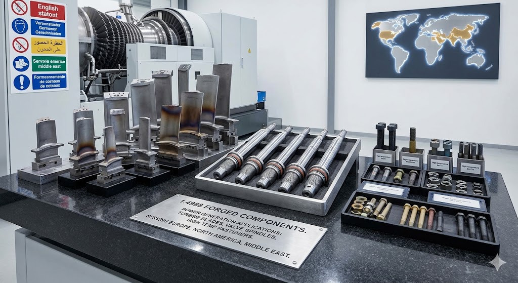
- Turbine & Power Generation Forgings: Rotor shafts, turbine discs, nozzle rings, guide vane rings, labyrinth seal rings, impeller blanks, coupling flanges; all orientations of property testing available
- Valve & Pipeline Forgings: Valve spindles, valve stems, valve bodies, bonnet forgings, gate discs, bypass valve seats; forged-and-machined to full dimensional drawing
- Pressure Vessel & Reactor Forgings: Cylinder shells, dome heads, nozzle stubs, manway frames, tube sheets, flange forgings, transition pieces; per ASME VIII, EN 13480, PED 2014/68/EU
- High-Temperature Fasteners: Forged and machined studs (double-ended, single-ended), hex bolts, hex nuts, stud bolts, socket head cap screws; thread class 6H/6g per ISO; diameters M8–M120; per ASTM A193 Grade B8S or client specification
- Precision CNC-Machined Forgings: Any of the above with full precision machining, internal bores, keyways, splines, serrations, threads, grooves, surface treatments (passivation, pickling, electropolishing) per client specification
Storage, Handling & Preservation of 1.4988 Forgings: Best Practices for Long-Term Integrity
Incorrect storage of 1.4988 forgings before installation can cause surface contamination, pitting initiation and mechanical damage that may only manifest during service. Our preservation and packing procedures are designed for the full duration from manufacturing to installation, including sea freight, port storage and construction site warehousing.
Critical Storage Rules
- No contact with carbon steel: Store on rubber-padded timber pallets or stainless steel racks. Direct contact between 1.4988 and carbon steel equipment (chains, slings, forks, frames) deposits iron particles that initiate rust pitting on the austenitic surface within days in humid environments. Remove iron contamination by passivation with 20% nitric acid before installation.
- Chloride source isolation: Storage in coastal, marine or de-icing salt environments requires full hermetic wrapping. Chloride deposited on 1.4988 surfaces initiates pitting corrosion at temperatures above 60°C in service. For components installed in industrial areas with airborne chloride, passivation inspection before installation is mandatory.
- Hydrogen embrittlement caution for high-hardness sections: 1.4988 fasteners in the high end of the hardness range (250–260 HBW) require careful attention during pickling and passivation to avoid hydrogen uptake. Use inhibited acid solutions; restrict acid contact time to <30 minutes; follow with alkaline rinse to neutralise residual acid.
- Long-term storage (>6 months): Apply thin film of food-grade or neutral mineral oil to all machined surfaces. Re-inspect VCI packaging integrity at 6-month intervals. Replace dessicant bags every 12 months. Photograph and document condition at each inspection for insurance and client handover records.
Our Standard Export Packing
- VCI (Volatile Corrosion Inhibitor) polyethylene bag wrapping: prevents atmospheric corrosion for up to 24 months without surface contact
- Foam rubber end caps and inter-component separators for multiple-piece shipments
- Moisture-proof plywood crates with internal desiccant bags and humidity indicator cards
- Steel banding with rubber edge protectors for large rings; foam support cradles for long shafts
- Photographic condition record at packing stage, appended to shipping documentation
- All markings stencilled on external crate surfaces: PO number, material grade, component serial, gross weight, centre of gravity, lift point locations
Global Project References: 1.4988 Forgings Proven in Critical Service Worldwide
Our 1.4988 X8CrNiMoVNb16-13 forgings are installed in critical high-temperature industrial systems on six continents. All project summaries below are based on actual supply references, with commercially sensitive details withheld.
European Union — Ultra-Supercritical Power Generation
Standards: EN 10222-5, EN 10204 3.2, PED 2014/68/EU, EN 13480
For 800MW and 1000MW USC steam turbine upgrade projects across Germany, Italy and the Netherlands, we supplied complete sets of 1.4988 valve spindles, guide vane rings, labyrinth seal rings and rotor shaft forgings, operating continuously at 600°C / 285 bar. All supplied in +P condition, UT Class 4 per EN 10228-3, with EN 10204 3.2 certification co-ordinated with client-nominated third-party inspection bodies. Components have been in stable long-term operation with no material-related failures reported to us.
North America — Sour Service Oil & Gas
Standards: NACE MR0175 / ISO 15156, ASTM, API 6A, ASME B16.34
For deep-water wellhead and Christmas tree equipment in the Gulf of Mexico and offshore Nova Scotia, we manufactured X8CrNiMoVNb16-13 seamless rolled rings, forged valve bodies and pressure-rated fasteners for API 15K (103 MPa) service in H₂S-containing environments. NACE MR0175 hardness compliance (max 22 HRC equivalent) verified by survey on each forging, accepted by clients' NORSOK-compliant QA systems.
Middle East — Mega Refinery Strategic Supply
Standards: NACE MR0175, ASTM, client owner-engineer project specifications
Over a five-year strategic supply agreement, we delivered more than 2,400 metric tons of 1.4988 seamless rings, hydrocracker reactor internals, distillation column shell forgings and high-temperature valve bodies for mega refinery projects in Saudi Arabia and the UAE. Third-party inspection was co-ordinated with client-nominated inspection bodies throughout. All documentation was submitted to and accepted by client owner-engineers. Full material traceability documentation was maintained throughout the supply programme.
Southeast Asia — Ultra-Supercritical Power Programme
Standards: EN 10222-5, ASTM, IEC 60034, national power generation codes
As a forging supplier to multiple major EPC contractors in the region, we supplied 1.4988 rotor shafts, blade disc forgings, valve spindles and seamless rings for 20 × 660MW and 4 × 1000MW USC thermal power units across Thailand, Indonesia, Vietnam and the Philippines. Components have been in continuous commercial operation for 3–8 years with no material-related in-service failures reported to us.
Australia — Mining Infrastructure & Power Generation
Standards: AS/NZS standards, ISO 9001, EN 10204 3.2
For a major Western Australian mining operator, we manufactured X8CrNiMoVNb16-13 impeller shafts and wear rings for high-pressure mineral slurry pumps. The choice of 1.4988 over 316 stainless was driven by the requirement for higher yield strength (to resist shaft deflection under ore slurry load) combined with adequate corrosion resistance in the mineral acid slurry environment at elevated temperature. Chemical and mechanical testing was conducted by a client-nominated testing laboratory, confirming compliance with project requirements.
South America — Petrochemical & Hydroelectric Projects
Standards: ASTM, EN, Petrobras N-1678, IEC 60034
For Petrobras refinery expansion in Brazil and copper mining energy infrastructure in Chile, we supplied 1.4988 flanges, valve bodies, pressure vessel nozzles and seamless rings. All products were supplied to client-specified Petrobras-standard requirements. Chilean client inspection was co-ordinated with a client-nominated local inspection representative; ASTM certifications were accepted by the Owner Engineer.
Quality Management System & Full Certification Support
Our ISO 9001:2015 certified QMS covers the full production scope from raw material procurement through final dispatch, with documented Inspection Test Plans (ITPs), control plans and hold points at each critical manufacturing stage. Third-party surveillance audits are conducted annually; our quality records are available for client review during supplier qualification audits.
In-House Testing Capabilities
- OES chemical analysis: all elements in <3 min per heat verification
- C/S combustion analysis (LECO): precise carbon control for Nb/C ratio compliance
- Inert gas fusion for N/O/H measurement
- Universal tensile testing to 600 kN; elevated temperature tensile testing available through accredited partner laboratory
- Charpy impact testing at -196°C to +300°C (cryogenic to elevated temperature)
- Brinell, Vickers and Rockwell hardness testing; automated hardness mapping
- SEM + EDS for precipitate characterisation and failure investigation — available through accredited materials laboratory partner
- Optical metallography: grain size, inclusion rating, phase identification, precipitate distribution
Complete MTC Package Contents
- PO number, drawing number, client spec reference
- Heat number, batch quantity, forging serial numbers
- Ladle analysis with EN 10222-5 limit comparison
- Product analysis (finished forging sample)
- Heat treatment records: furnace ID, temperatures, soaking times, cooling methods, chart references
- RT + elevated temperature mechanical test results (actual values, not just pass/fail)
- Hardness survey results per forging
- UT report: method, standard, acceptance class, individual indication records
- PT report: method, penetrant type, acceptance level, result
- Grain size report + representative micrograph (if specified)
- Dimensional inspection report vs drawing tolerances
- EN 10204 3.1 or 3.2 certificate, signed and stamped
Our forging material grades fully comply with ASTM, AMS, AISI, API, DIN, EN, JIS and other international standards. Third-party inspection coordination by our dedicated quality team ensures smooth witness inspection scheduling with TÜV, SGS, Bureau Veritas, Lloyd's Register, RINA or any client-nominated authority.
Frequently Asked Questions — 1.4988 X8CrNiMoVNb16-13 Forgings
1.4988 (X8CrNiMoVNb16-13) has no direct ASTM or UNS equivalent. It is most closely compared to A286 (UNS S66286) for precipitation hardening capability and to AISI 310S for oxidation resistance — but it outperforms both in the 600–750°C service range due to its balanced Nb-V carbonitride precipitate system and controlled nitrogen content. Never substitute 316H (1.4919) or 321H (1.4878) — those grades lack the Nb+V precipitation mechanism and achieve only 40–50% of 1.4988's creep rupture strength at 600°C, creating a potentially catastrophic under-design in creep-loaded applications.
X8CrNiMoVNb16-13 provides continuous scaling resistance up to 750°C and stable design creep strength for sustained mechanical loading up to 650°C (based on 10⁵-hour rupture data). Short-term excursions to 800°C are permissible without significant oxidation or phase instability. For applications involving frequent thermal cycling, the thermomechanical fatigue (TMF) life — not static creep — becomes the governing design criterion, and may reduce the effective operating temperature limit depending on cycle frequency and amplitude.
Sigma phase formation in 1.4988 is substantially retarded compared to duplex and ferritic grades due to its high Ni content (12.5–14.5%) and fully austenitic (ferrite-free) matrix. Field metallographic examination of 1.4988 turbine spindle sections at 100,000-hour overhaul intervals consistently shows only trace sigma phase (<1 vol%), with impact toughness remaining above 40 J at room temperature. Sigma phase is not a limiting factor for correctly heat-treated 1.4988 within standard 200,000-hour design life frameworks. However, components approaching or exceeding 100,000 hours should undergo fitness-for-service assessment including Charpy impact testing to quantify any toughness reduction.
Stress relaxation cracking (SRC, also called reheat cracking) occurs when welding residual stresses relax at elevated temperature by intergranular crack propagation rather than by plastic flow, because the intragranular precipitate network (VN+NbCN) is too strong to accommodate the relaxation strain within grains. 1.4988 has moderate SRC susceptibility at service temperatures above 550°C in highly restrained weld joints. Management strategies include: minimising weld restraint by design; using low-heat-input TIG welding for critical joints; grinding weld cap and root to remove stress raisers; and performing post-weld full re-solution annealing followed by re-aging for maximum SRC resistance. Partial stress relief at 600–650°C without prior re-annealing reduces residual stress but does not eliminate SRC risk in heavily restrained joints.
Field PMI of 1.4988 uses portable XRF or OES. The key discriminating elements are: Vanadium (V) 0.60–0.85% (absent in 316H, 321H, 347H, 310S) and Niobium (Nb) >0.50% (absent in 316H, 321H, 310S; also present in 347H but without V). The simultaneous detection of both V ≥ 0.50% and Nb ≥ 0.50% by XRF is a near-unique fingerprint for 1.4988 among common austenitic stainless steel grades. Nitrogen (0.060–0.140%) is a further confirming element but requires combustion analysis or portable OES, not standard XRF. Molybdenum at 1.10–1.50% helps distinguish 1.4988 from 310S (no Mo) and 321H (no Mo).
Yes. EN 10204 3.1 mill test certificates — covering full ladle composition, heat treatment furnace records, mechanical test results (RT and elevated temperature as required), NDT reports and dimensional inspection — are standard for all 1.4988 supply. EN 10204 3.2 certification with independent third-party witness inspection is available on request, coordinated with client-nominated third-party inspection bodies (such as TÜV, SGS, Bureau Veritas, Lloyd's Register, RINA or equivalent) upon client request. Our quality coordination team provides advance hold point notification and witness scheduling to all parties.
Upgrade from 1.4988 to nickel superalloys when any of the following apply: (1) sustained design temperature exceeds 700°C — 1.4988 creep strength falls below practical pressure vessel code allowables at this level, requiring Incoloy 800H or 800HT; (2) creep rupture strength requirement exceeds 45–50 MPa at 650°C / 10⁵h — Alloy 617 or 625 are the next step; (3) sulphidising high-temperature environments above 700°C create Type I hot corrosion that Cr₂O₃-forming austenitic steels cannot resist; (4) extreme TMF cycle count (>500 cycles/year) combined with peak temperatures above 650°C — Alloy 718 provides the higher fatigue strength needed; (5) high-chloride process fluid contact at sustained temperature above 100°C — Alloy 625 or C-276 provide SCC immunity where 1.4988 is susceptible. For all conditions below these thresholds, 1.4988 provides superior engineering value at 30–50% lower material cost than nickel superalloys.
We produce 1.4988 X8CrNiMoVNb16-13 seamless rolled rings up to 6,000 mm outer diameter, 1,500 mm height and 30 metric tons per piece. Custom contoured cross-sections — L-rings, T-rings, stepped, asymmetric flange and bevel-face profiles — are rolled directly using profiled tooling for optimal grain flow alignment. Forged bars to 2,000 mm diameter and shafts to 15,000 mm length are also available. Turbine disc forgings to 1,500 mm OD via ESR ingot route for UT Class 4.
For 1.4988 seamless rolled rings above 2,000 mm OD and 5 metric tons, the realistic lead time from purchase order receipt to delivery is 14–20 weeks. This includes: ingot casting and solidification (3–4 weeks), ingot homogenisation and heating (1 week), ring rolling and forging (1–2 weeks), two-stage heat treatment (3–4 weeks), rough machining (1–2 weeks), UT and PT inspection (1–2 weeks), final machining (2–3 weeks) and documentation preparation (1 week). Very large rings above 4,000 mm OD require 20–28 weeks. Contact our sales team at enquiry stage to discuss schedule acceleration options including use of pre-stocked ingot material.
Request a Custom 1.4988 X8CrNiMoVNb16-13 Forging Quotation
Jiangsu Liangyi provides technically superior, fully documented 1.4988 X8CrNiMoVNb16-13 forging parts for the most demanding global industrial applications. Whether your project requires a single prototype shaft forging or a multi-year strategic supply programme for large seamless rings, our engineering and commercial teams deliver the optimal solution — from material specification through final certified delivery.
To receive a detailed quotation, please provide: material specification (EN 10222-5 or project spec.), forging geometry and drawings if available, single-piece weight and quantity, supply condition (+P standard), certification level (3.1 or 3.2), NDT class and acceptance standard, elevated temperature test requirements, and required delivery date. Our technical sales team will confirm feasibility and provide an indicative lead time within 24 hours.
Inquiry Email: sales@jnmtforgedparts.com
Phone / WhatsApp: +86-13585067993
Official Website: www.jnmtforgedparts.com
Factory Address: Chengchang Industry Park, Jiangyin City, Jiangsu Province, China
Response Commitment: Technical confirmation within 24 hours; quotation within 3 working days for standard sizes
Request a Quote Now →