1.4435 (X2CrNiMo18-14-3) Forging Parts | Custom Stainless Steel Forgings Manufacturer
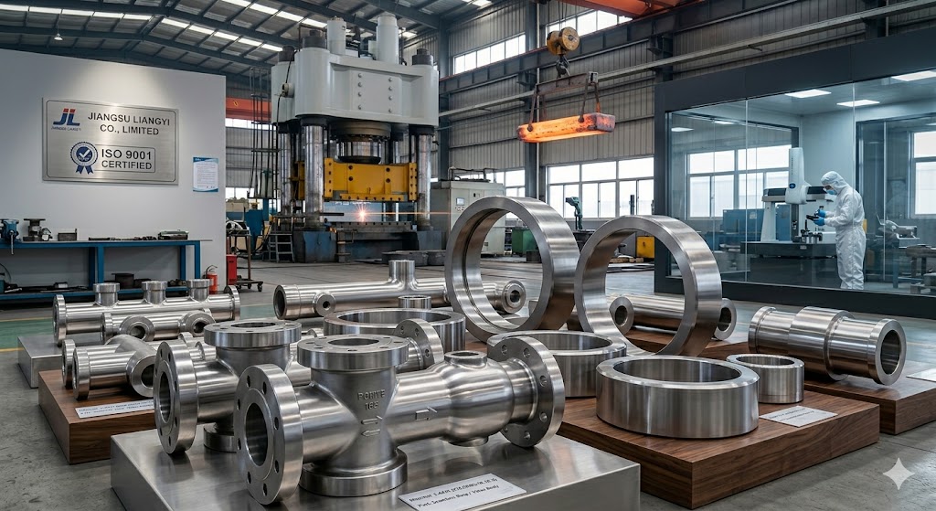
Jiangsu Liangyi Co.,Limited — founded 1997, Jiangyin City, Jiangsu Province, China — is an ISO 9001:2015 certified open die forging and seamless ring rolling manufacturer specializing in 1.4435 (X2CrNiMo18-14-3) stainless steel. With an 80,000 m² factory, 120,000-ton annual capacity, and a dedicated 1.4435 process established over 25 years, the company supplies custom forged components for valve, oil & gas, petrochemical, cryogenic, and nuclear power industries across 50+ countries, with EN 10204 3.1/3.2 documentation support, in-house chemical and mechanical testing, and 24/7 English-language engineering support.
Quick Reference: 1.4435 (X2CrNiMo18-14-3) Forging Parts
- Material Designation: EN 1.4435 | X2CrNiMo18-14-3 | UNS S31603 (high-alloy) | DIN 17440
- Equivalent Standard: ASTM A182 Grade F316L (superior alloy floor), EN 10088-3
- Carbon Content: ≤ 0.03% (Ultra-Low — prevents sensitization in as-welded condition)
- Molybdenum (Mo): 2.5% – 3.5% | Nickel (Ni): 12.5% – 15.0%
- PREN Formula: %Cr + 3.3×%Mo + 16×%N = 26 – 30 (superior pitting resistance)
- Operating Temperature: Cryogenic -196°C to elevated +400°C (continuous service)
- Tensile Strength: 500 – 700 MPa | Yield Strength: ≥ 200 MPa | KV2 at -196°C: ≥ 60 J
- Solution Annealing: 1050 – 1100°C + rapid water quench (factory-controlled ±5°C)
- Max Forging Size: OD up to 6,000 mm (rings) | Weight up to 30 tons | Length up to 15 m
- Certifications: ISO 9001:2015 | EN 10204 3.1 (std) / 3.2 (on request) | PED / API / ASME documentation available
- NDT: UT / PT / RT — in-house testing lab | TÜV / SGS / BV / DNV witness inspection supported
- Manufacturer: Jiangsu Liangyi Co.,Limited — Jiangyin, Jiangsu, China (Est. 1997)
- Lead Time: 15–20 days (forging + HT) | 25–35 days (+ machining + full inspection)
- Global Reach: 50+ countries | Incoterms: EXW, FOB, CIF, CFR, DAP, DDP
Understanding 1.4435 (X2CrNiMo18-14-3): The Metallurgical Case for Choosing This Grade
When procurement engineers specify 1.4435, they are often working from a data sheet that lists chemistry limits and mechanical minima. What the data sheet rarely explains is why the alloy works the way it does — and what manufacturing decisions at the forging stage either preserve or destroy those properties. Having produced over 12,000 tons of 1.4435 forgings since 2005, our engineering team has developed a practical, test-backed understanding of this material that we share here to help you specify and buy more confidently.
The Sensitization Risk and Why Ultra-Low Carbon Is Not Optional
The defining characteristic of the 1.4435 grade family is the carbon ceiling of ≤ 0.03%. This is not an arbitrary number. Carbon in austenitic stainless steel precipitates as chromium carbide (Cr₂₃C₆) at grain boundaries when the metal is held in the 450–850°C temperature range — a phenomenon called sensitization. As chromium migrates from the matrix to form carbides, the grain boundary zones become chromium-depleted to below the 10.5% threshold required for passive oxide film formation. The result is a steel that appears fully corrosion resistant on the surface but has micro-zones of effectively unprotected iron scattered throughout its grain boundary network — a condition that leads to intergranular corrosion (IGC) failure.
In a forging context, this matters in two scenarios: first, during the forging process itself, where the material passes through sensitization-range temperatures during cooling after forming; and second, after delivery, when the customer welds the forging into an assembly. With ≤ 0.03% C, the carbide precipitation kinetics are dramatically slowed — there simply is not enough carbon available to form a continuous grain-boundary carbide network at normal welding heat input levels. This is why 1.4435 forgings can be welded into pressure vessels without mandatory post-weld heat treatment (PWHT), a critical manufacturing advantage over higher-carbon 1.4401 (316) forgings. Our internal controls target C ≤ 0.025% — tighter than the standard requirement — to provide an additional safety margin for components with complex weld joint geometries.
How Molybdenum and Nickel Work Together in 1.4435
The elevated molybdenum content (2.5–3.5%) of 1.4435 acts through two distinct mechanisms. First, Mo incorporates into the passive oxide film and shifts its breakdown potential to more positive values — meaning the surface film ruptures only under more aggressive electrochemical conditions, directly extending service life in chloride-bearing media such as seawater, brine, and process streams containing HCl. Second, Mo refines grain boundary chemistry during solidification, reducing the likelihood of preferential grain boundary attack even if minor sensitization occurs during subsequent processing.
The pitting resistance equivalent (PREN) provides a single-number ranking: PREN = %Cr + 3.3 × %Mo + 16 × %N. For 1.4435 with Cr at 17.5%, Mo at 3.0%, and N at 0.06%: PREN = 17.5 + (3.3 × 3.0) + (16 × 0.06) = 17.5 + 9.9 + 0.96 = 28.4. By contrast, a typical 1.4404 (316L) with Cr 17.0%, Mo 2.2%, N 0.05% yields PREN = 17.0 + 7.26 + 0.80 = 25.1. This gap of approximately 3 PREN points translates to a significant increase in critical pitting temperature (CPT) — in our corrosion testing using ASTM G48 Method C (ferric chloride solution), 1.4435 forgings consistently outperform 1.4404 by 8–12°C in CPT, providing meaningful additional margin in process streams operating near or above ambient temperature.
The elevated nickel (12.5–15.0%) serves a different purpose: it stabilizes the austenite phase, suppresses delta ferrite formation during solidification and high-temperature forging, and enhances low-temperature toughness by reducing the ductile-to-brittle transition temperature well below -196°C. For cryogenic applications — LNG equipment, cold storage compressors, liquid nitrogen handling systems — the nickel advantage of 1.4435 over 1.4404 directly supports the Charpy impact energy requirement of ≥ 60 J at -196°C mandated by EN 10088-3 and PED Annex I.
🔬 Manufacturer's Insight — Delta Ferrite: The Hidden Quality Variable
One quality parameter most suppliers never discuss: delta ferrite content. During solidification of austenitic stainless steel, a small amount of body-centered cubic ferrite (δ-ferrite) forms and partially transforms to austenite on cooling. Residual delta ferrite above approximately 3–5% ferrite number (FN) degrades intergranular corrosion resistance, reduces low-temperature impact toughness, and creates directional anisotropy in mechanical properties. We control delta ferrite to FN < 2% in all 1.4435 forgings through precise Cr/Ni equivalent management at the EAF-AOD stage, verified by feritscope measurement per EN ISO 8249. This is a process control step that distinguishes material forged by specialists from generic bar or casting supply.
1.4435 vs Competing Grades: When to Specify What
| Parameter | 1.4435 (X2CrNiMo18-14-3) | 1.4404 (316L Standard) | 1.4401 (316 Standard C) | 1.4462 (Duplex 2205) |
|---|---|---|---|---|
| Carbon (%) | ≤ 0.03 | ≤ 0.03 | ≤ 0.08 | ≤ 0.03 |
| Mo (%) | 2.5 – 3.5 | 2.0 – 2.5 | 2.0 – 2.5 | 3.0 – 3.5 |
| Ni (%) | 12.5 – 15.0 | 10.0 – 13.0 | 10.0 – 13.0 | 4.5 – 6.5 |
| PREN (typical) | 26 – 30 | 23 – 26 | 22 – 25 | 32 – 36 |
| IGC Resistance (as-welded) | Excellent — no PWHT needed | Good | Requires PWHT or 321/347 stabilization | Good |
| Toughness at -196°C | ≥ 60 J (EN 10088-3) | ≥ 40 J (typical) | Poor — BCC phase risk | Limited — 475°C embrittlement risk |
| Stress Corrosion Cracking (SCC) Risk | Low in moderate Cl⁻ | Moderate | Higher | Very Low |
| Weldability | Excellent | Very Good | Moderate | Good with procedure control |
| Relative Material Cost vs 1.4404 | +12–18% | Baseline | –5 to –8% | +20–30% |
| Best For | Severe corrosion, cryogenic, heavy welding | General corrosive service | Non-critical corrosive service | High-pressure, H₂S, seawater |
The table above reflects a practical decision framework we share with clients when they are evaluating material options. 1.4435 occupies a specific niche: it outperforms 1.4404 significantly in demanding service conditions, at a cost premium that is justified by the performance margin and simplified welding procedure requirements. Where SCC resistance under sustained stress in high-chloride environments is the primary concern, duplex grades such as 1.4462 warrant evaluation — though their lower toughness at sub-zero temperatures and sensitivity to sigma phase embrittlement above 280°C require careful engineering assessment.
Why 1.4435 Critical Components Must Be Forged: A Process Engineering Perspective
Purchasers occasionally ask whether a cast 1.4435 component or a component machined from hot-rolled bar stock could substitute for an open die forging. The answer depends on the application, but for pressure-containing, rotating, or structurally critical parts, the differences are material and measurable.
Casting vs. Forging: The Microstructural Argument
Casting produces components by pouring molten metal into a mold. The solidification front advances inward, creating a dendritic microstructure with coarse grains, segregation bands (chromium, molybdenum, and nickel are not uniformly distributed at the microscale), and casting porosity — gas voids and shrinkage cavities that UT inspection can detect when large, but which at sub-millimeter scale remain undetectable and act as fatigue crack initiation sites. Cast 1.4435 components also exhibit lower ductility (A typically 35–38% vs ≥40% for forgings) and variable toughness from part to part.
Forging refines this cast structure through thermomechanical working. The combination of heat (above the austenite recrystallization temperature) and compressive deformation breaks down dendritic arms, homogenizes the distribution of alloying elements, closes porosity through diffusion bonding, and produces equiaxed, refined grains with a controlled crystallographic texture (fiber flow) aligned to the component's principal stress axes. The result is demonstrably superior: our forged 1.4435 components consistently achieve Charpy impact values 15–25% above the EN 10088-3 minimum at -196°C — energy that is not achievable in cast equivalents of the same chemistry.
Machined Bar vs. Open Die Forging
Hot-rolled or continuously cast stainless bar stock is a legitimate starting point for small, simple components. However, for parts with cross-sections above approximately 150 mm diameter, the center of a rolled bar exhibits significantly coarser grain structure, higher inclusion content, and inferior toughness compared to the surface — because the thermomechanical working during rolling is concentrated near the surface and does not fully penetrate to the bar core. A flange, valve body, or heavy shaft machined from bar stock therefore carries an inherent property gradient from surface to core that open die forging eliminates by working the entire cross-section uniformly.
Additionally, bar stock machining cuts across the metal fiber flow (grain flow lines), exposing them at machined surfaces where corrosive media can preferentially attack along the flow direction — a phenomenon called end-grain corrosion, particularly relevant for 1.4435 components in chloride service. Open die forging, by contrast, produces components where the fiber flow follows the shape of the part — flowing around holes, along flanges, and conforming to the external profile — so no machined surface cuts across the flow lines and exposes them to the environment.
📐 From Our Engineering Team — Forging Ratio: Why ≥ 4:1 Matters for 1.4435
We apply a minimum forging reduction ratio of 4:1 (cross-sectional area before vs. after forging) for all 1.4435 components. This threshold is established by our corrosion testing data: forgings produced at ratios below 3:1 — a practice sometimes used to meet delivery schedules — retain residual dendritic segregation in the Cr and Mo distribution, reducing effective PREN by 1.5–2 points at the micro-scale and producing inconsistent pitting behavior in ASTM G48 tests. At ratios of 4:1 and above, our spectrometric analysis of multiple forging cross-sections confirms homogeneous Cr and Mo distribution (standard deviation <0.15% across the cross-section), and ASTM G48 Method A test results are consistent batch-to-batch. We document the achieved reduction ratio in the Forging Process Card provided with every order.
Our Full 1.4435 Forging Production Process: From Raw Steel to Certified Delivery
Every 1.4435 forging we produce passes through a documented, quality-gated production sequence. Unlike manufacturers who purchase billet from the open market and begin at the forging stage, we operate a full in-house metallurgical chain from steelmaking through final delivery inspection — giving us quality visibility and control at every step that external-billet suppliers cannot match.
Raw Material: EAF → AOD → VOD Steelmaking
We produce 1.4435 ingots and billets in our 30-ton Electric Arc Furnace (EAF), refined by Argon Oxygen Decarburization (AOD) to achieve the ultra-low carbon target of ≤ 0.025% while maintaining precise Cr, Mo, and Ni alloy balance. For demanding applications — nuclear power, aerospace, subsea — we additionally apply Vacuum Oxygen Decarburization (VOD), which lowers dissolved oxygen and nitrogen content further, and optionally Electroslag Remelting (ESR) to eliminate macro-inclusions and achieve the most homogeneous possible ingot structure. Each heat is spectrometrically analyzed in our in-house laboratory before being released for forging. A melt traceability number is assigned at this stage and maintained on all documents through final delivery.
Billet Preparation and Incoming UT Inspection
Before forging begins, all ingots and billets undergo 100% volumetric ultrasonic testing (UT) per EN 10228-3 / ASTM A388 to identify any solidification-related internal defects — segregation, pipe voids, or inclusions — that would propagate through the forging process. Billets failing our internal UT acceptance criteria (stricter than EN acceptance class 3) are downgraded or rejected at this stage, before any manufacturing value is added. This pre-forging UT is a step many forges skip because it requires a dedicated phased-array UT system compatible with round billet geometry — our PAUT-equipped billet inspection station handles sections from 150 mm to 1,200 mm diameter.
Controlled Forging: Temperature, Reduction, and Die Strategy
1.4435 austenitic stainless steel presents specific forging challenges compared to carbon steel. First, it work-hardens rapidly — flow stress increases significantly with deformation, requiring higher press tonnage per unit area than equivalent carbon steel billets, which is why we use 4,000T and 6,300T hydraulic presses for heavy 1.4435 sections rather than the smaller presses that suffice for carbon steel of similar weight. Second, the forging temperature window is narrower: we maintain billet surface temperature in the 1,100–1,200°C range during forming, monitored by contact thermocouples and pyrometer cross-checks at each press stroke sequence. Forging below 1,000°C risks adiabatic shear band formation and inadequate recrystallization; forging above 1,220°C risks incipient melting at grain boundaries (hot shortness), leading to surface cracking. We reheat billets between forging passes when temperature drops below 1,050°C — a discipline that adds time but is non-negotiable for product integrity.
Seamless Ring Rolling (for Ring Products)
For 1.4435 seamless rolled rings, the forged preform (donut-shaped bloom) is transferred hot to our radial-axial ring rolling mill immediately after preliminary open die shaping. Our ring rolling equipment ranges from 1 m to 5 m capacity, producing rings from 500 mm to 6,000 mm outer diameter. The key quality parameter in ring rolling is maintaining consistent wall thickness uniformity around the circumference — variation above ±3% introduces residual stress concentrations that degrade fatigue life. We measure rolled ring geometry at multiple angular positions using laser profilometry before transferring to heat treatment, and any ring outside our ±2% wall uniformity internal standard is corrected in a final sizing pass.
Solution Annealing and Rapid Quenching
After forming, all 1.4435 forgings are solution annealed in our batch atmosphere furnaces at 1,080 ± 10°C. The holding time is calculated as a minimum of 1 hour per 25 mm of cross-section, never less than 2 hours absolute, to ensure complete dissolution of any carbides or sigma phase that formed during the thermomechanical process. Following the hold, components are transferred within 30 seconds to the water quench tank — this rapid cooling rate (targeting ≥ 3°C/second through the 850–450°C sensitization range) is critical to suppress carbide re-precipitation during cooling. For very large forgings above 15 tons, we use forced water circulation in the quench tank and strategic orientation of the component to achieve uniform cooling — avoiding differential cooling that would impose residual thermal stresses. Full time-temperature records are archived for every heat treatment batch and provided as part of the EN 10204 MTC package.
CNC Machining to Drawing Tolerances
After heat treatment and dimensional verification of the forged blank, components requiring machining proceed to our CNC machining division. Machining austenitic stainless steel requires different strategies than carbon steel: lower cutting speeds, higher feed rates, aggressive coolant application, and sharp carbide tooling to avoid work-hardening the surface ahead of the cutting edge. Our machinists are trained specifically in 1.4435 toolpath strategies that maintain Ra 1.6–3.2 μm surface finish as standard on non-sealing surfaces and Ra 0.8 μm on valve sealing faces and flange contact surfaces, without the burnishing artifacts that would obscure surface-breaking defects from subsequent PT inspection. CMM verification is performed to EN ISO 10360 standards after machining completion.
Full-System Quality Inspection and Documentation
The final inspection stage integrates results from: in-house chemical analysis (OES and CS analyzer), in-house mechanical testing (tensile, impact, hardness), NDT (UT, PT, MT, RT per client specification), dimensional CMM inspection to drawing, visual inspection per EN ISO 10228-1, intergranular corrosion testing per ASTM A262 Practice E (when specified), pitting corrosion testing per ASTM G48 (when specified), and hydrostatic pressure testing (when specified). All results are compiled into a traceable EN 10204 3.1 or 3.2 Material Test Certificate linked to the forging heat number, furnace batch number, and machining work order — providing complete cradle-to-delivery traceability that survives decades of plant operation and regulatory audit.
Full Range of Custom 1.4435 (X2CrNiMo18-14-3) Forged Products
Our 1.4435 forging range covers the full spectrum of open die forged shapes and seamless rolled ring geometries, with single-piece weights from 30 kg to 30 tons and ring diameters from 200 mm to 6,000 mm. All products are manufactured in strict compliance with EN, ASTM, DIN, API, and client-specific standards, with one-stop CNC machining and inspection to eliminate secondary supplier handoffs in your supply chain.
1.4435 Forged Bars, Round Bars, and Step Shafts
We produce custom X2CrNiMo18-14-3 forged bars in round, flat, square, rectangular, and hexagonal cross-sections, including hollow bars and multi-diameter step shafts. Typical applications include pump and compressor shafts, valve stems, actuator rods, structural tie rods, and manifold bodies for chemical and oil & gas service. Our bar forging capacity: diameter range 80 mm – 2,000 mm, length range 200 mm – 15,000 mm, maximum single-piece weight 30 tons. All forgings are available with 100% UT per ASTM A388 or EN 10228-3 (Class 3 or better), with guaranteed mechanical property compliance in the longitudinal, transverse, and short-transverse orientations when specified.
1.4435 Seamless Rolled Forged Rings
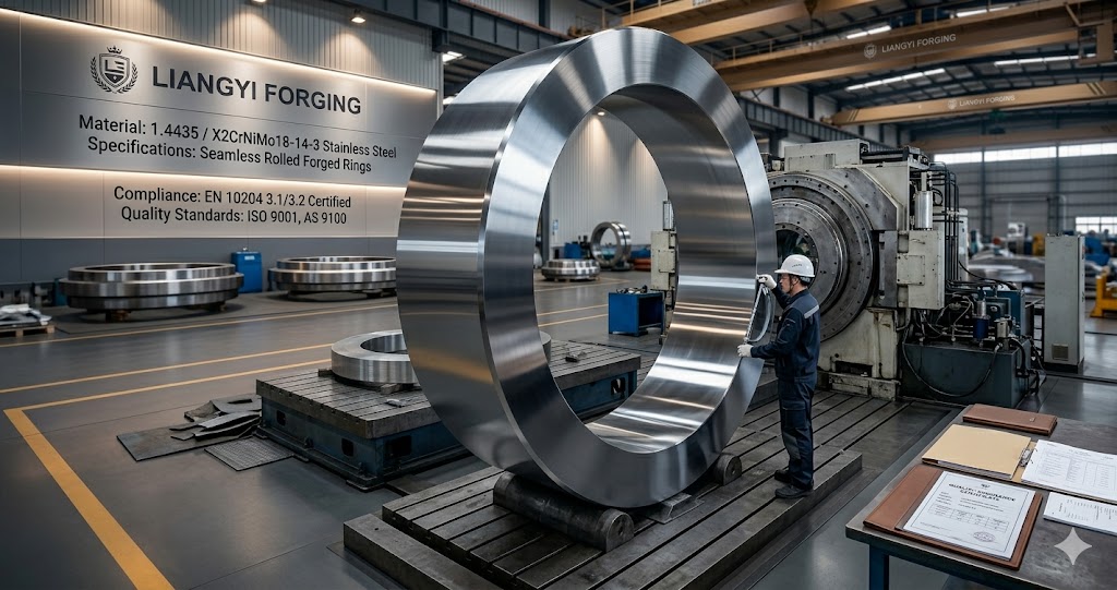
Our seamless rolled ring range is one of the broadest in China for stainless steel grades: outer diameter 200 mm to 6,000 mm, wall thickness 20 mm to 1,000 mm, height 50 mm to 2,500 mm, maximum weight 30 tons. Ring profiles include flat rings, profiled/contoured rings (L-sections, T-sections, stepped profiles), gear blanks, slewing bearing races, large-bore flanges, and pressure vessel head courses. The seamless ring rolling process delivers circumferential fiber flow alignment that maximizes hoop strength and fatigue resistance — critical for rotating machinery, pressure vessels, and valve seat retention rings subjected to cyclic loading. We offer rings in the as-rolled + solution annealed + quenched condition, with optional rough bore/face turning and full CMM dimensional report.
1.4435 Forged Shafts and Rotating Components
We manufacture custom X2CrNiMo18-14-3 solid and hollow shafts — gear shafts, crankshafts, pump shafts, agitator shafts, turbine shafts, spindle shafts, and valve spindles — with diameter up to 1,800 mm and length up to 15 meters. Our forging approach for large shafts uses successive drawing operations with intermediate reheats, ensuring the critical core-to-surface ratio of mechanical properties meets specification throughout the cross-section. For shafts requiring tighter dimensional tolerances (h6–h9), we machine immediately post-quench while thermal residual stresses are minimized, then verify straightness by CMM and laser alignment. Runout tolerance of ≤ 0.1 mm/m is achievable on shafts up to 5 m in length.
1.4435 Seamless Hollow Forgings: Cylinders, Sleeves, and Pressure Vessels
Seamless hollow forgings — cylinders, sleeves, bushings, thick-wall pressure vessel shells, heat exchanger outer shells, and hydraulic actuator bodies — are manufactured by punching, mandrel drawing, and reaming to achieve wall uniformity and guaranteed absence of weld seams. Outer diameter up to 3,000 mm, wall thickness 20–600 mm, height up to 3,000 mm. The seamless construction eliminates the preferential corrosion attack path at weld heat-affected zones that is the primary failure mode of welded shell fabrications in 1.4435 service. Internal surfaces are available with machined surface finish Ra ≤ 3.2 μm or mirror-polished Ra ≤ 0.8 μm for pharmaceutical, food-grade, and ultra-high-purity process applications.
1.4435 Valve and Oil & Gas Forged Components
Our valve and oil & gas forging range serves the broadest range of critical service conditions: ball valve bodies (2" – 60"), butterfly valve shafts and discs, gate valve bonnets and wedges, check valve casings, globe valve bodies, cryogenic LNG valve bodies and stems, wellhead casing heads, tubing heads, Christmas tree components, subsea equipment blocks, and choke valve trim. All oil & gas components are manufactured against API 6A, 16A, 17D, and NACE MR0175/ISO 15156 material and dimensional requirements as applicable to the customer's purchase specification. We maintain documented Material Qualification Records (MQRs) for 1.4435 at multiple qualification levels, and support client-side API Monogram licensee qualification processes.
Bespoke and Complex Geometry 1.4435 Forgings
We also produce non-standard geometries: tube sheets for shell-and-tube heat exchangers (holed pattern layout with tight inter-hole ligament ratios), baffle plates, forged-and-drilled manifold blocks, large-bore reducing flanges, eccentric reducers, forged impeller blanks for centrifugal pumps and compressors, nuclear equipment support forgings, and one-off prototype components for equipment manufacturers developing new products. Our engineering team supports customers from concept through drawing issue, providing formal Design for Forgeability (DFF) reviews that identify geometric features that complicate forging or inspection — and proposing geometry modifications that reduce cost without compromising function.
Chemical Composition of 1.4435 (X2CrNiMo18-14-3) — Standard vs. Our Internal Control
The following table compares the EN 10088-3 chemistry limits for 1.4435 against our internal production control standards. Our tighter internal limits are not marketing language — they reflect our process capability demonstrated across 15,000+ heat analyses, and they provide measurable product performance benefits including higher average PREN, more consistent mechanical properties batch-to-batch, and lower scatter in corrosion test results.
| Element | EN 10088-3 Limit | Our Internal Control | Why Our Limit Matters |
|---|---|---|---|
| Carbon (C) | ≤ 0.030% | ≤ 0.025% | Additional IGC resistance margin; wider safe welding window |
| Silicon (Si) | ≤ 1.00% | 0.20 – 0.60% | Excessive Si promotes sigma phase; lower Si improves weldability |
| Manganese (Mn) | ≤ 2.00% | 1.00 – 1.80% | Mn stabilizes austenite; controlling the ceiling avoids excessive sulfide inclusion density |
| Phosphorus (P) | ≤ 0.045% | ≤ 0.030% | Lower P reduces hot-shortness risk during forging; improves weld toughness |
| Sulfur (S) | ≤ 0.030% | ≤ 0.010% | MnS inclusions act as pitting initiation sites; lower S directly raises effective PREN |
| Chromium (Cr) | 17.00 – 19.00% | 17.50 – 18.50% | Controlled floor ensures minimum PREN; ceiling avoids sigma phase precipitation tendency |
| Molybdenum (Mo) | 2.50 – 3.50% | 2.80 – 3.20% | High Mo floor maximizes pitting resistance; tight window ensures batch-to-batch PREN consistency |
| Nickel (Ni) | 12.50 – 15.00% | 13.00 – 14.50% | Ensures austenite stability; supports cryogenic toughness performance |
| Nitrogen (N) | ≤ 0.110% | 0.040 – 0.080% | Controlled N adds PREN (×16 coefficient); upper ceiling avoids porosity in welds |
Mechanical Properties of 1.4435 Forgings: Required Minima and Our Typical Achieved Values
The following table presents EN 10088-3 minimum requirements alongside our typical achieved values across production lots. The difference reflects the combined benefit of our tighter chemistry control, optimized forging reduction ratio (≥4:1), and precisely controlled solution annealing cycle.
| Mechanical Property | EN 10088-3 Minimum | Our Typical Achieved | Test Standard |
|---|---|---|---|
| Tensile Strength (Rm) | 500 – 700 MPa | 540 – 670 MPa | EN ISO 6892-1 |
| Yield Strength (Rp0.2) | ≥ 200 MPa | Typically 220 – 270 MPa | EN ISO 6892-1 |
| Elongation (A) | ≥ 40% | Typically 45 – 55% | EN ISO 6892-1 |
| Reduction of Area (Z) | ≥ 60% | Typically 65 – 75% | EN ISO 6892-1 |
| Hardness | ≤ 215 HB | Typically 155 – 190 HB | EN ISO 6506-1 |
| Charpy Impact (KV2 at -196°C) | ≥ 60 J | Typically 90 – 140 J | EN ISO 148-1 |
| Charpy Impact (KV2 at +20°C) | Not mandated by standard | Typically 160 – 220 J | EN ISO 148-1 (when specified) |
Important Note on Sample Orientation: Mechanical test specimens are extracted longitudinal to the forging direction as standard per EN 10088-3. For components where transverse or short-transverse properties are critical (thick flanges, heavy-wall pressure vessels, subsea blocks), we offer multi-orientation test programs — transverse and short-transverse tensile and impact tests — on request. Transverse properties in our forgings typically run 85–90% of longitudinal values, reflecting the high forging reduction ratios we apply. This data is available on request before order placement.
Global Industry Applications: Failure Analysis Behind Each Choice
The following section describes not just where 1.4435 is used, but why it was selected over alternatives — often after a documented field failure with a lower-specification material. This context is drawn from project briefs and customer technical discussions over 25+ years of supply to critical industries worldwide.
Valve Manufacturing: Why LNG Cryogenic Valves Demand 1.4435 Over 1.4404
LNG storage and transfer systems operate at -162°C to -196°C, where austenitic stainless steels are among the few metallic materials that retain adequate ductility and toughness. The failure mode that drove many European valve manufacturers to mandate 1.4435 over standard 1.4404 was documented in the 1990s–2000s: leaking valve spindles and bonnet connections traced to preferential grain boundary attack in heat-affected zones of 1.4404 forgings that had been welded without PWHT. The slightly higher carbon content permitted by the broader 1.4404 specification (some heats approaching 0.028–0.030% C) was sufficient, combined with the welding thermal cycle, to produce sensitized zones that suffered intergranular corrosion when condensation and trace chloride contamination occurred during plant maintenance cycles. Switching to 1.4435 with C ≤ 0.025% internal control — and verified ASTM A262 Practice E testing — eliminated this failure mode from the affected installations.
Today we supply over 15,000 sets per year of 1.4435 forged cryogenic valve components to manufacturers in Germany, Italy, France, and the Netherlands, covering LNG transfer, liquid nitrogen, liquid oxygen, and liquid argon service. Components are 100% PT inspected, Charpy impact tested at -196°C (reported as actual values, not pass/fail), and issued with EN 10204 3.1 or 3.2 MTC. For clients assembling CE-marked pressure equipment under PED 2014/68/EU, we provide the EN 10204 material documentation package required by the applicable Conformity Assessment Module.
Oil & Gas: Sour Service Wellhead Components
Sour service environments — containing H₂S at partial pressures above 0.3 kPa per NACE MR0175/ISO 15156 — impose additional material requirements beyond simple corrosion resistance: resistance to sulfide stress cracking (SSC) and hydrogen-induced cracking (HIC). For austenitic stainless steels, compliance with NACE MR0175 in Regions 3 (most severe) requires hardness ≤ 22 HRC (approximately 237 HB) and documentation of solution annealing heat treatment. Our 1.4435 forgings in solution annealed condition consistently achieve 155–190 HB, comfortably within NACE compliance, and our EN 10204 MTC includes the solution anneal record and hardness certificate required for NACE MR0175 documentation audits.
For onshore oilfield projects in Saudi Arabia, the UAE, and Kuwait — where brine with chloride concentrations of 100,000–200,000 ppm and temperatures of 60–100°C combine with H₂S and CO₂ to create a severely multi-corrosive environment — 1.4435 is specified for wellhead adapters, tubing hangers, and Christmas tree upper completions where weight and threading requirements preclude duplex or super-duplex grades. Our forgings for this application are manufactured to the material chemistry and mechanical requirements referenced in API 6A, with NACE TM0177 Solution A hydrogen sulfide corrosion test data available on qualification lots when specified by the client's purchase order.
Petrochemical & Chemical: Heat Exchanger Tube Sheets at Scale
One of the most dimensionally demanding 1.4435 products we manufacture is large tube sheets for shell-and-tube heat exchangers. These are flat or slightly curved discs — up to 2,500 mm OD, 150–300 mm thick, drilled with 2,000–8,000 precision holes to a pattern specified by the heat exchanger designer — used in sulfuric acid plants, chlor-alkali facilities, pharmaceutical API processes, and seawater desalination systems.
The challenge specific to tube sheets is that drilling thousands of closely spaced holes leaves thin ligaments (the wall of material between adjacent tube holes) that are susceptible to preferential corrosion if the base material has any compositional banding or poor corrosion resistance consistency. We address this through: (1) forging the disc blank at ≥4:1 reduction ratio to eliminate compositional banding; (2) sampling corrosion test coupons from the perimeter of each tube sheet forging before hole-drilling commences, verifying ASTM G48 CPT performance; and (3) performing final UT after drilling to confirm no subsurface laminar defects are exposed at the bore surfaces. This three-stage quality approach means our tube sheets maintain consistent pitting resistance across the entire drilled pattern, not just at the edges.
Nuclear Power: Coolant Pump Components and the Special Requirements
Nuclear power applications for 1.4435 involve the most demanding documentation, traceability, and inspection requirements of any commercial industry. Reactor coolant system components — pump casings, impellers, suction and discharge nozzle forgings, seal housing rings — must comply with KTA 3201.1 (Germany), ASME Section III Class 1 or 2, RCC-M (France), or equivalent national nuclear codes, all of which impose requirements beyond EN 10088-3 alone: grain size certification (ASTM grain size ≥ 5), restricted delta ferrite content (FN ≤ 5%), Level C or better UT acceptance (EN 10228-4 Class 4 or equivalent), complete heat number and charge traceability, and batch-specific qualification of forging and heat treatment parameters.
We have supplied 1.4435 forged components to nuclear power plant projects in China and Southeast Asia since 2012, maintaining project-specific Quality Plans approved by plant owner quality departments. Our experience navigating nuclear-level documentation requirements — Inspection and Test Plans (ITPs), First Article Inspections (FAIs), Witness Inspection Schedules — is available to new clients entering nuclear supply chains for the first time.
Marine & Offshore: Seawater Pump Components and Long-Term Immersion Service
Seawater at ambient temperature contains approximately 19,000–22,000 ppm chloride — well above the threshold that causes rapid pitting of standard 316L (1.4404) in stagnant or low-velocity conditions. For seawater pump casings, impellers, shaft sleeves, and valve bodies that experience periods of stagnant immersion (during maintenance, shutdown, or tidal cycling), the PREN requirement to avoid pitting in ambient seawater is generally taken as PREN ≥ 26 — the minimum achievable floor for 1.4435, which our average production achieves at PREN 27–29. Standard 1.4404 with PREN 23–25 is insufficient for this application without supplemental coatings or cathodic protection.
For offshore applications — subsea production equipment, drilling risers, topside seawater systems — we produce 1.4435 forgings to DNVGL-OS-F101, DNVGL-ST-F101, and ISO 13628 requirements, coordinating with DNV GL, Bureau Veritas, and Lloyd's Register surveyors for 3.2 inspection. Supplemental testing — CTOD (crack tip opening displacement) fracture toughness, fatigue crack growth rate testing, and corrosion fatigue testing in seawater — is available through our external testing partner network for projects requiring proof of fitness-for-purpose beyond standard certification.
Full-Process Quality Control and In-House Testing Capabilities
Our quality management system is ISO 9001:2015 certified, but our actual practice exceeds the standard's minimum requirements at every stage. Below is a description of what we actually do — not what the certificate requires — because buyers deserve to understand the real quality barrier their incoming material passes through.
Spectrometric Chemical Analysis (Every Heat)
Every heat of 1.4435 steel we produce is analyzed by our in-house optical emission spectrometer (OES) — analyzing all 9 major elements (C, Si, Mn, P, S, Cr, Mo, Ni, N) plus trace elements (Cu, Co, Ti, Al, Nb, V, B) — within 4 hours of tapping. A second analysis is performed after forging from samples taken from the top and bottom of the ingot or from both ends of a large billet, to verify homogeneity. Results deviating by more than 0.05% from the target for any major element trigger a material review board hold and are not released for machining without engineering review and written approval. The carbon-sulfur analyzer runs a parallel verification for C and S. All analysis certificates are dual-signed by lab technician and QC manager before issue.
In-House Mechanical Testing Laboratory
Our in-house mechanical testing laboratory is equipped and operated under our ISO 9001:2015 quality management system for tensile testing, impact testing, and hardness testing of metallic materials. Testing capacity includes: 100-ton universal testing machine for tensile and compression testing, Charpy pendulum impact tester capable of testing down to -196°C using a liquid nitrogen cryostat, Brinell and Rockwell hardness testers, microhardness tester, and creep testing rigs available for extended test programs. All test equipment is calibrated at scheduled intervals traceable to national measurement standards, with calibration certificates maintained and available for client audit. For clients requiring third-party witnessed or independently verified test results, we coordinate with external accredited laboratories including SGS, Bureau Veritas, and TÜV on request.
Non-Destructive Testing: What We Actually Inspect
Our NDT is performed by personnel certified to Level II qualification. We do not subcontract NDT to external agencies for standard inspections; all UT, PT, and RT are performed by our own certified staff using calibrated equipment with current calibration certificates traceable to national standards. For UT, we use phased-array ultrasonic (PAUT) systems for complex geometries and large cross-sections, providing electronic scan data storage and full traceability of scan paths — not just the inspector's hand-written worksheet. UT scan data is archived for 5 years after delivery and available for customer audit or re-analysis.
Global Compliance & Certification: Regional Nuances That Matter
Compliance is not one-size-fits-all. The regulatory requirements for 1.4435 forged components differ meaningfully between the EU, North America, Middle East, and Australia, and navigating these differences requires forging supplier experience that many manufacturers lack. Below is a summary of the key regional compliance considerations we have encountered across 25+ years of global supply:
European Union: PED 2014/68/EU and Material Certification
EU Pressure Equipment Directive (PED) 2014/68/EU categorizes pressure equipment by fluid group and pressure rating, determining the required Conformity Assessment Procedure (Modules). For Category III and IV pressure equipment — the most critical — materials must be sourced from EU-harmonized material specifications (EN 10088-3 for 1.4435) or qualified through a European Approval of Materials (EAM). Our EN 10204 3.1 certificates issued against EN 10088-3 are directly accepted by EU notified bodies (CE Marking bodies) for PED Cat III and IV applications. For EN 10204 3.2 requirements — mandatory for some notified bodies on critical applications — we coordinate TÜV Rheinland or Bureau Veritas witness inspection at our factory, with the inspector's countersignature on the MTC completing the compliance chain.
North America: ASME BPVC and ASTM A182
ASME Boiler and Pressure Vessel Code (BPVC) Section II Part A specifies forged austenitic stainless steel under ASTM A182. 1.4435 maps to ASTM A182 Grade F316L, but with higher alloy floor requirements — a nuance that must be confirmed in the purchase specification (by calling out minimum Mo ≥ 2.5% and minimum Ni ≥ 12.5%) to ensure the supplied material actually delivers 1.4435-equivalent performance rather than standard F316L. We can supply A182 F316L MTCs with supplemental chemistry certification to EN 10088-3 1.4435 alloy floors simultaneously — providing a single document that satisfies both ASME Section VIII Div.1/Div.2 and EN pressure vessel codes for multinational projects.
Middle East: ARAMCO, ADNOC, and KOC Project Specifications
National oil companies in the Middle East — Saudi Aramco, ADNOC, and Kuwait Oil Company — maintain their own material and fabrication specifications that often impose requirements beyond API and ASME standards. Aramco specification SAES-A-112 and SAES-W-009, for example, impose additional restrictions on Mo content (minimum 2.5% enforced as a composition requirement, not just a specification limit), hardness ceilings for sour service (SMYS ≤ 415 MPa and HRC ≤ 22), and mandatory vendor approval processes. We have supplied 1.4435 forgings to Aramco-approved fabricators for onshore projects, and our factory documentation — QMS manual, calibration records, personnel qualification records — meets Aramco Source Inspection requirements without requiring pre-qualification audits.
Why Jiangsu Liangyi: What 25 Years of 1.4435 Forging Experience Actually Means
Most forging suppliers claim experience. The claims that matter are the ones backed by documented process parameters, test data, and reference projects. Here is a factual account of what distinguishes our 1.4435 offering:
- Full metallurgical chain, in-house: EAF-AOD steelmaking → forging (2,000T / 4,000T / 6,300T hydraulic presses; 1T–5T electro-hydraulic hammers) → ring rolling (1 m – 5 m capacity mills) → solution annealing (10+ intelligent atmosphere furnaces, ±5°C temperature uniformity) → CNC machining (turning centers up to ⌀3,500 mm, floor boring mills, 5-axis machining centers) → in-house chemical and mechanical testing → NDT (PAUT, PT, RT in-house). No subcontracting of critical process steps.
- 1.4435-specific process documentation: Our Forging Process Cards for 1.4435 include heat-specific forging temperature logs, reduction ratio calculations, quench water temperature records, and solution anneal time-temperature charts. This is auditable data — not a checkbox — and it is provided to clients who require it for their own QMS records.
- Capacity that supports project scale: 120,000 tons per year total capacity means we can absorb a 500-ton 1.4435 frame contract without displacing other customers — a supply reliability consideration that matters to EPC contractors managing project schedules with no float.
- English-language engineering team available 24/7: Our sales engineers hold metallurgical engineering degrees and are fluent in English. They can review your drawing, calculate forging stock allowances, identify inspection access challenges, and issue a Forging Design Review (FDR) report before you commit to tooling or production. This is not a call center; it is an engineering dialogue.
- Prototype-to-production continuity: When you qualify a prototype forging from us, the production forgings use the same melt schedule, forging process card, and heat treatment parameters — not a "similar" process. Our QMS requires a change notification and re-qualification if any process parameter changes by more than a defined tolerance. This continuity eliminates the qualification re-work that arises when suppliers produce prototypes by one route and production by another.
- Third-party inspection welcome: Client representatives, notified body inspectors (TÜV, BV, DNV), and appointed third-party inspection agencies (SGS, Intertek) are welcome on-site at our factory for witness inspections. We maintain a designated inspection area with full access to production records, test equipment, and raw material traceability documents. We have never refused a witness inspection request.
Frequently Asked Questions About 1.4435 Forging Parts
The following questions reflect real enquiries from our global client base — procurement engineers, project managers, and metallurgists who are evaluating 1.4435 forged components for the first time or comparing suppliers. We answer with the specificity that engineering decisions require.
There is no fixed MOQ. We regularly produce single prototype pieces from 30 kg for client engineering validation — the same melt control and process discipline applies to a 30 kg prototype as to a 300-ton production frame. Economically, single-piece custom forgings are priced to include full setup and testing cost, which reduces the unit cost significantly at quantities above 10–20 pieces. We provide itemized quotations that show material, forging, heat treatment, machining, and inspection cost components separately, so clients can make informed make-buy decisions on which value-add steps to have us perform vs. handle in-house. For recurring annual contracts, we offer annual volume pricing tiers and material pre-purchasing programs that lock in competitive pricing across multi-month delivery schedules.
Lead time depends on three factors: stock status of 1.4435 billet, forging complexity, and inspection scope. With stock billet and a straightforward geometry (round bar or disc), forging + solution annealing + EN 10204 3.1 MTC can be completed in 12–15 working days. Adding CNC rough machining extends to 20–25 working days. Full machining + 100% UT + PT + CMM dimensional report adds another 5–8 working days, landing typical complex orders at 28–35 working days total. For large seamless rolled rings above 3 m OD, or components requiring ESR premium billet (which must be ordered), allow 35–50 working days. EN 10204 3.2 with third-party witness inspection adds 5–7 working days for inspector scheduling and countersigning. We provide a binding Gantt-chart production schedule with milestone confirmations (billet ready, forging complete, heat treatment complete, inspection complete) at order confirmation, and send progress updates when each milestone is achieved — not just when there is a problem.
Yes, EN 10204 3.2 certification is available for all 1.4435 forging orders and is coordinated entirely by our in-house QA team so that the client's only action is to specify 3.2 at the time of enquiry. The process: (1) Client specifies which inspection organization they wish to use — TÜV Rheinland, Bureau Veritas, DNV, Lloyd's Register, SGS, Intertek, or their own nominated inspector are all regularly used at our factory; (2) Our QA team contacts the inspection organization to set up a master inspection agreement and schedule; (3) We notify the inspector when key hold or witness points are reached (typically: billet UT, heat treatment completion, mechanical testing, final NDT, dimensional check); (4) The inspector witnesses or reviews the designated activities and countersigns the test certificate; (5) The countersigned 3.2 MTC is issued as part of the shipment documentation package. For clients who use EN 10204 3.2 routinely across many suppliers, we can align with their preferred inspection agency blanket agreements to minimize per-order setup costs.
Custom drawing manufacturing is our primary business — approximately 80% of orders are produced from client-supplied drawings with no standard catalog equivalent. We accept DWG, DXF, STEP, IGES, PDF, and SolidWorks native formats. Our mandatory Drawing Review process — performed by a metallurgical or mechanical engineer within 48 hours of drawing receipt — checks: (1) forgeability (can the geometry be achieved by open die forging, or does it require closed die or machining-from-bar?); (2) machining stock allowances (are they sufficient for the heat treatment distortion expected for this section thickness?); (3) NDT access (are there blind pockets or undercuts that prevent UT probe placement for 100% coverage?); (4) dimensional tolerance vs. forging capability (can tolerances be held by forging alone, or is finish machining required?); (5) surface finish specification alignment with our machining capabilities. The output is a written Drawing Review Report issued to the client before production commences — flagging any questions or recommended drawing modifications, and confirming acceptance when everything is satisfactory. No production starts on an unreviewed drawing.
Both are ultra-low carbon (≤0.03% C) austenitic stainless steels, but 1.4435 has higher alloy floors: Mo 2.5–3.5% vs 2.0–2.5%, and Ni 12.5–15.0% vs 10.0–13.0% for 1.4404. In forging practice, these differences translate as follows: (1) Pitting resistance: PREN 26–30 for 1.4435 vs 23–26 for 1.4404. A 3-point PREN advantage translates to approximately 8–12°C higher critical pitting temperature in ASTM G48 testing — meaningful for components operating above ambient temperature in chloride media. (2) Cryogenic toughness: 1.4435 forged components consistently achieve KV2 ≥ 90 J at -196°C in our testing; equivalent 1.4404 forgings typically achieve 55–75 J, sometimes marginal against the ≥60 J requirement. (3) Welding: Both grades benefit from ultra-low carbon for IGC resistance, but the higher Mo content of 1.4435 provides additional corrosion resistance in the heat-affected zone without PWHT. Upgrade recommendation: specify 1.4435 when (a) chloride concentration in the process stream exceeds 500 ppm at operating temperature, (b) operating temperature is above 40°C in any chloride-bearing environment, (c) the component will be welded in a production assembly without PWHT, or (d) service temperature falls below -100°C. For general purpose, non-welded, low-chloride applications, 1.4404 is cost-adequate — but the 12–18% material premium of 1.4435 is frequently justified by the elimination of corrosion maintenance costs over a 20-year plant life.
Austenitic stainless steel presents specific NDT challenges not present with ferritic or martensitic steels. Magnetic Particle Testing (MT) is not applicable because 1.4435 is non-magnetic in solution annealed condition (residual ferrite < 2 FN). Ultrasonic Testing (UT) of austenitic stainless forgings requires higher-frequency transducers (typically 5 MHz vs 2 MHz for carbon steel) and specific signal processing to address the high acoustic attenuation and grain noise (backwall scatter) characteristic of coarse-grained austenite — our PAUT systems include grain noise suppression algorithms that maintain sensitivity equivalent to EN 10228-3 Class 3 acceptance in sections up to 400 mm thickness. Penetrant Testing (PT) is highly effective for 1.4435 surface inspection and is our standard method for detecting surface-breaking cracks, laps, and cold shuts — we use fluorescent penetrant (Type 1, Method D, Sensitivity Level 2) rather than color contrast for improved detectability of fine cracks. Radiographic Testing (RT) is used for complex geometries where UT access is limited. We do not substitute less sensitive methods for convenience — if a component geometry requires RT to achieve full inspection coverage, we arrange it rather than issuing an NDT report with coverage limitations.
Yes. Our CNC machining division operates CNC turning centers (max swing ⌀3,500 mm, max between-centers distance 15,000 mm), vertical machining centers, horizontal boring mills, and 5-axis machining centers for complex geometries, all in a temperature-controlled workshop environment. 1.4435 machines differently from carbon steel due to its high work-hardening rate — the material's yield strength rises sharply with plastic deformation, meaning that dwell cuts (stopping the feed while the spindle runs) build up a hardened layer that degrades subsequent tool life and surface finish. Our machinists apply continuous chip-forming toolpaths, aggressive axial depth of cut (ADOC) relative to radial, TiAlN-coated solid carbide inserts, and high-pressure coolant directed at the cutting interface to flush chips and manage temperature. Standard surface finish: Ra 3.2 μm general; Ra 1.6 μm bearing and fit surfaces; Ra 0.8 μm valve sealing and flange gasket contact faces. Dimensional tolerance: IT7 (H7/h7 fits) as standard; IT6 available for precision fits on request. All machined dimensions are verified by our in-house CMM equipment to EN ISO 10360, with CMM reports issued in GD&T format per ASME Y14.5 or ISO 1101 as specified by the client.
We support all Incoterms 2020 delivery terms: EXW (Jiangyin factory gate), FCA, FAS, FOB (Shanghai Yangshan Deep Water Port or Ningbo Zhoushan Port — our standard loading ports), CFR, CIF, CPT, CIP, DAP, DDP. Our logistics team coordinates with freight forwarders experienced in heavy industrial cargo, including open-top containers for large-diameter rings, flat-rack containers for long shafts, and out-of-gauge breakbulk shipments for forgings above standard container dimensions. Typical sea freight transit: 25–32 days to Hamburg/Rotterdam, 28–35 days to Houston (via Panama Canal) or Los Angeles, 18–22 days to Dubai/Jebel Ali, 22–28 days to Port Klang/Singapore/Sydney. Air freight is available for urgent small components. Export documentation package — commercial invoice, packing list, bill of lading, certificate of origin, MTC, inspection certificates — is prepared in English and can include CE Declaration of Conformity, REACH/RoHS declaration, and customs tariff (HTS) classification data for smooth import clearance in regulated markets. We maintain comprehensive export compliance records and can provide end-use certificates required by customers in sensitive-industry supply chains.
Delta ferrite (δ-ferrite) is residual body-centered cubic ferrite that remains in austenitic stainless steel after solidification when the chromium equivalent exceeds the nickel equivalent by a sufficient margin. In 1.4435 specifically, the high chromium (17.5–19%) and relatively modest nickel (12.5–15%) create a balance that can produce 2–8% delta ferrite in as-cast material — which, if not controlled through forging and annealing, degrades two properties critical to 1.4435 selection criteria: first, delta ferrite is less corrosion resistant than the austenite matrix and creates micro-galvanic cells at ferrite-austenite boundaries that initiate pitting in chloride environments; second, delta ferrite reduces Charpy impact energy at cryogenic temperatures, which can cause some forgings to fail the ≥60 J at -196°C requirement if delta ferrite is not adequately suppressed. Our control strategy: (1) At EAF-AOD stage, we target Creq/Nieq ratio (using Schaeffler diagram) to land in the fully austenitic solidification zone with ≤2% predicted ferrite; (2) Forging at ≥4:1 reduction ratio above 1,050°C mechanically breaks up ferrite stringers; (3) Solution annealing at 1,080°C for the calculated hold time dissolves remaining ferrite into austenite; (4) Final ferrite content is measured by feritscope per EN ISO 8249, with our internal acceptance limit of FN ≤ 2. This result is reported in the MTC on request — if your application requires documentation of delta ferrite control, please specify this in the RFQ.
Request a Quotation for Custom 1.4435 (X2CrNiMo18-14-3) Forging Parts
Whether you are in the preliminary specification stage and need technical input, or ready to place a production order with a detailed drawing package, our engineering team is prepared to engage immediately. We commit to an initial engineering response within 4 business hours of enquiry receipt, and a complete commercial and technical quotation within 24 hours for standard enquiries.
To receive the most accurate quotation, please provide: your drawing (any format accepted), material specification requirement, quantity and delivery schedule, required certifications (3.1 or 3.2), NDT scope, any applicable project specifications, and your delivery port or destination. We will confirm receipt of your enquiry, acknowledge any missing information, and set a firm quotation delivery commitment at first response.
📧 Inquiry Email: sales@jnmtforgedparts.com
📞 Phone / WhatsApp (24/7 English): +86-135-8506-7993
📠 Fax: +86-510-86107550
🌐 Website: www.jnmtforgedparts.com
📍 Factory: Chengchang Industry Park, Jiangyin City, Jiangsu Province 214400, China